⏱ 25 min read
Using UML for API Design and Integration Architecture | Best Practices Sparx EA best practices
Learn how UML supports API design and integration architecture through clear modeling of services, data flows, interfaces, and system interactions. Explore practical best practices for scalable enterprise solutions. Sparx EA training
UML for API design, integration architecture, API architecture, UML diagrams, system integration, enterprise architecture, API modeling, software architecture, service design, interface design, data flow modeling, sequence diagrams, component diagrams, scalable API design how architecture review boards use Sparx EA
Introduction
In enterprise architecture, APIs are not just technical interfaces. They are products, contracts, and integration assets that connect core platforms, expose capabilities to partners, support digital channels, and allow teams to work together without creating tight coupling between systems. As integration estates expand across cloud services, SaaS platforms, legacy applications, event brokers, partner ecosystems, and workflow tools, the need for clear architectural communication increases. ArchiMate modeling best practices
UML still has a practical role in this environment. It is often associated with application design, but it remains equally useful in API and integration work when applied with restraint. The objective is not to model everything. The objective is to use a small number of diagrams to make the important decisions visible: service boundaries, ownership, dependencies, orchestration, runtime behavior, and the relationship between APIs, events, and data flows.
That wider view is often absent when teams move straight to implementation artifacts such as OpenAPI definitions, AsyncAPI contracts, gateway policies, or infrastructure code. Those artifacts are necessary, but they describe interfaces and platform settings rather than the architecture around them. They do not show how services fit together, where trust boundaries sit, which system owns business state, or how an API participates in a larger process. UML helps fill that gap by giving teams a common way to discuss intent, structure, and operating assumptions.
This matters because API design rarely stands alone. A single API may rely on identity services, gateways, transformation layers, event platforms, workflow engines, and downstream systems with very different latency and reliability characteristics. Teams can agree on endpoints and still disagree on ownership, responsibility, or runtime expectations. UML gives business stakeholders, security teams, platform teams, architects, and delivery teams a shared set of views for resolving those questions.
Used well, UML also improves governance. It exposes duplicate capabilities, hidden point-to-point dependencies, misplaced orchestration, and brittle runtime coupling that may not be obvious from a contract definition alone. An architecture review board, for example, may discover that a proposed “customer API” is really a cross-domain orchestration service with direct dependencies on CRM, billing, and consent systems. That is not a documentation issue. It is an architectural finding.
This article takes a practical view of UML for API design and integration architecture. The point is not to use every UML artifact. It is to choose the few that help teams communicate intent, test design decisions, and reason about enterprise integration more clearly.
Why UML Still Matters for API and Integration Architecture
Modern API delivery depends on lightweight, implementation-facing artifacts: OpenAPI, AsyncAPI, gateway configuration, service mesh policy, Terraform modules, and platform automation. All of these are useful. None of them, by themselves, explains the broader architecture. They define contracts and controls, but they do not show the shape of the integration landscape: boundaries, ownership, dependencies, orchestration, and runtime behavior across systems.
That broader view matters because enterprise integration is rarely a simple request-response exchange. APIs often sit inside mixed interaction models that combine synchronous calls, asynchronous events, batch movement, workflow, and manual intervention. If teams document only the contract, they can miss the more consequential questions:
- Where does orchestration occur?
- Which system owns the business state?
- Which interactions must be synchronous, and which are synchronous only out of habit?
- What happens when downstream services fail?
- Which concerns belong in the API layer, and which belong in workflow, domain, or integration platforms?
UML remains useful because it helps answer those questions before they become embedded in code, gateways, and operational processes.
This becomes especially important when an API is only the visible face of a more complex capability. A customer profile API may look straightforward externally while internally coordinating identity resolution, consent checks, entitlement validation, and reads from multiple systems of record. The interface specification can describe payloads and operations, but it does not easily show whether the API is acting as:
- a thin access layer,
- a composite service,
- an orchestration point, or
- an anti-corruption boundary around legacy systems.
That distinction affects latency, resilience, ownership, and long-term change cost.
UML also matters because many integration failures come from unclear boundaries rather than poor endpoint design. In large organizations, the recurring problems are usually ambiguous responsibility, shared services with no clear owner, and APIs that quietly become mediation hubs. A structural UML view can show whether an API belongs to a business domain, a reusable platform capability, or an ungoverned integration layer that has accumulated too much logic.
It also supports trade-off discussions that machine-readable contracts do not express particularly well. Architects often need to compare direct access with mediation, orchestration with choreography, canonical with domain-specific models, and synchronous with event-driven interaction. UML makes those choices visible. A sequence diagram can expose excessive round trips. A deployment diagram can reveal avoidable cross-network dependencies. An activity diagram can show process logic living in the wrong layer. In an IAM modernization effort, for instance, a sequence diagram may make it clear whether token validation, consent checks, and entitlement decisions belong in the gateway, a shared identity service, or each domain API.
So UML does not compete with API specifications or automation. It complements them. It links local interface design to enterprise structure and runtime behavior. The rest of this article focuses on the UML views that are most useful in practice and how they support design, integration modeling, and lifecycle governance.
Core UML Diagrams for API Design and Service Interaction
Not every UML diagram adds equal value in API work. A small, consistent set usually delivers most of the benefit. In practice, five or six diagram types cover the majority of architectural concerns.
1. Use Case Diagrams: Framing Consumers and Outcomes
Use case diagrams are useful early in API design because they clarify who the API exists for and what outcomes it is meant to support. In API architecture, the actors are often not people but channels, internal applications, partner platforms, batch processes, or event-driven consumers.
This view helps teams test assumptions:
- Is the API designed for one primary consumer group or several incompatible ones?
- Is a supposedly reusable service actually tailored to a single channel?
- Are secondary consumers driving the design more than the primary business outcome?
This is often where over-generalization first becomes visible.
2. Component Diagrams: Defining Services and Dependencies
Component diagrams are usually the most valuable UML artifact for API architecture. They show which services provide which interfaces, what dependencies exist, and where gateways, brokers, workflow engines, identity services, and transformation layers sit.
They are particularly useful for distinguishing whether an API is:
- a domain service,
- a composite service,
- a façade over legacy systems, or
- an integration utility presented as a business capability.
That distinction shapes governance, ownership, resilience expectations, and lifecycle management.
A realistic example is a retail enterprise exposing a Product Availability API. The interface looks like a simple lookup service, but the component model reveals dependencies on inventory, store operations, pricing, and a cache invalidation service. That changes the design discussion immediately. What appeared to be a domain API may actually be a composite service with strict runtime dependencies and broader failure modes.
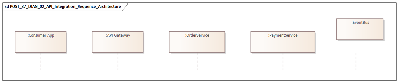
3. Sequence Diagrams: Showing Runtime Interaction
If component diagrams explain structure, sequence diagrams explain behavior. They show who calls whom, in what order, and under what conditions. For APIs, many of the most important risks are temporal rather than structural.
A sequence diagram can reveal:
- chatty downstream interaction,
- serial dependencies that increase latency,
- misplaced orchestration,
- retries and fallback behavior,
- policy enforcement and token validation steps,
- synchronous dependencies hidden inside an apparently asynchronous design.
These concerns often matter more than endpoint shape.
Consider a claims submission API in an insurance platform. A sequence diagram may show the API calling identity, policy validation, fraud screening, and document services one after another before returning a response. The contract itself may look clean, but the runtime sequence exposes why response times are unstable and why the API fails whenever one noncritical dependency slows down.
4. Activity Diagrams: Modeling End-to-End Flow
Activity diagrams complement sequence diagrams by focusing on flow logic rather than message order. They are useful when an API participates in onboarding, order fulfillment, claims handling, approvals, or case management.
They help teams determine whether business flow belongs:
- inside the API layer,
- in a workflow engine,
- in domain services,
- or in event-driven coordination.
This is often the clearest way to spot orchestration that has become too centralized.
5. State Machine Diagrams: Clarifying Lifecycle Semantics
State machine diagrams are valuable when APIs expose resources with meaningful lifecycle states, such as orders, subscriptions, payments, tickets, or provisioning requests.
They help define:
- valid transitions,
- operations allowed in each state,
- the effect of asynchronous updates,
- consumer expectations across the lifecycle.
That reduces ambiguity in API behavior and aligns interface semantics with business rules.
For example, in a telecom provisioning API, a service order may move through Submitted, Validated, Scheduled, In Progress, Completed, and Failed states. Without a state model, consumers often make incorrect assumptions about when cancellation is allowed or whether “completed” means technically provisioned or commercially active.
6. Deployment Diagrams: Making Runtime Topology Visible
Deployment diagrams show where services actually run and how gateways, brokers, clusters, and back-end platforms connect. This matters for latency, trust boundaries, residency, availability, and operational risk.
A service may look clean in a logical view but become fragile once its runtime topology is understood. A payment API that appears straightforward in a component model may, in deployment terms, depend on a cloud-hosted gateway, an on-premises fraud engine, a regional tokenization service, and a mainframe settlement platform across multiple network zones. That has direct implications for resilience and support.
Choosing the Minimum Useful Set
Most API initiatives do not need all of these diagrams in the same depth. A practical minimum usually includes:
- a use case view for consumers and purpose,
- a component view for boundaries and dependencies,
- a sequence or activity view for behavior,
- and a deployment or state view where runtime or lifecycle semantics matter.
The sections that follow focus mainly on component, sequence, and activity views because they tend to provide the greatest value in design reviews, integration analysis, and governance discussions.
Using UML to Define API Contracts, Boundaries, and Responsibilities
The most valuable use of UML in API architecture is not simply to show that systems interact. It is to clarify what an API is responsible for, what it hides, and what it should never own. Most enterprise API problems stem from unclear boundaries rather than from contract syntax. fixing Sparx EA performance problems
Start with Capability, Not Endpoints
A sound review starts with a simple question: what capability does this API represent? A component or package view is often the best place to answer it.
That shifts the discussion away from “what endpoints are needed?” and toward questions such as:
- What business capability is being exposed?
- Which domain owns it?
- Which responsibilities belong inside this service boundary?
- Which concerns should stay outside it?
If a customer API starts to absorb product eligibility logic, billing lookups, and marketing preference management, the model quickly shows that the service is no longer a coherent domain API. It has become a convenience layer spanning several domains.
Separate External Contract from Internal Realization
One of UML’s strongest uses is to distinguish the consumer-facing contract from the internal realization behind it. An API may present a stable business-friendly interface while internally depending on volatile systems, transformations, and policy checks.
By modeling the provided interface separately from the internal components, architects can test whether the API genuinely shields consumers from implementation churn. This is especially relevant in modernization programs, where APIs often serve as anti-corruption layers between digital channels and legacy platforms.
A useful review question is simple: does the contract expose business semantics, or does it leak internal system structures, codes, and process assumptions?
Make Responsibility Explicit
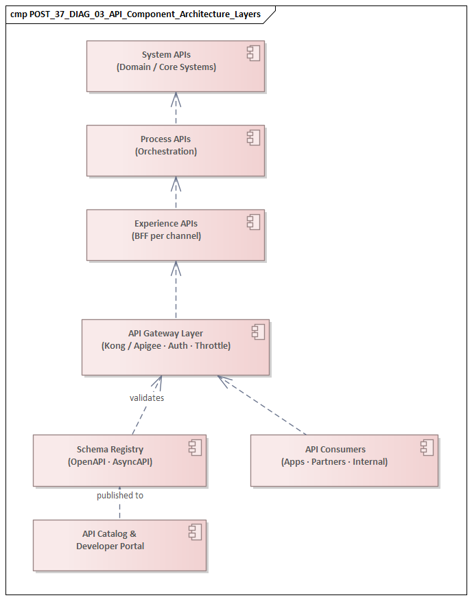
Component and activity diagrams are particularly helpful for showing where logic actually sits. That helps define whether an API is functioning as:
- a system API exposing a record system,
- a process API coordinating interactions,
- an experience API tailored to a channel,
- or a domain API representing a business capability.
The labels are less important than the clarity. Problems arise when one API tries to play all of these roles at once.
A component model can show where transformation and composition occur. A sequence or activity model can show where decision-making and orchestration sit. Taken together, these diagrams reveal whether the API layer is becoming too heavy.
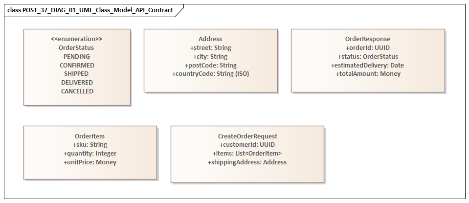
Define Semantic Boundaries
UML can also help with the semantics of the contract. Light domain modeling, often using class-style diagrams sparingly, can identify the core entities, value objects, and relationships that shape the API vocabulary.
The aim is not code design. It is to test whether the contract reflects business language or simply mirrors database tables and legacy message formats.
This helps teams spot when consumers are being exposed to:
- persistence concepts,
- source-system identifiers,
- technical status flags,
- or internal structures that should remain hidden.
If those elements dominate the model, the API boundary probably needs refinement.
Boundary Questions UML Should Help Answer
A pragmatic UML review should make the following questions visible:
- Who owns the data exposed by this API?
- Which business rules are enforced here?
- Which dependencies are hidden and which are surfaced?
- What back-end changes should not force contract changes?
- Which responsibilities belong in the API layer, and which belong in workflow, domain services, or event-driven processes?
The value lies less in the diagram itself than in the discipline of making those responsibilities explicit.
Modeling Integration Architecture Across Systems, Events, and Data Flows
Once API boundaries are clear, the next step is to place them within the wider integration architecture. APIs are only one part of enterprise integration. Business capabilities are usually delivered through a mix of synchronous APIs, asynchronous events, file transfer, workflow, and data movement. UML is useful here because it can bring these mechanisms into a coherent set of views.
A practical way to model integration is across three dimensions: system relationships, interaction style, and data movement.
1. System Relationships
A component diagram provides the structural view of the integration landscape. It shows participating systems, gateways, event brokers, transformation services, workflow engines, and trust boundaries.
This is where architects can identify whether the organization relies on:
- direct point-to-point connections,
- centralized mediation,
- domain-aligned integration hubs,
- or an inconsistent combination of patterns.
That structural view often reveals concentration risk, such as a single integration service becoming the dependency path for too many critical flows.
2. Interaction Style
Sequence diagrams remain useful for request-response scenarios, especially where an API triggers multiple downstream calls or spans several systems within one transaction. But not every integration is synchronous.
In event-driven architecture, the model should show asynchronous publication, subscription, delayed processing, retries, dead-letter handling, and compensation where relevant. Sequence diagrams can still support this if asynchronous interactions are shown explicitly rather than implied. A Kafka-based order flow, for example, may show the Order API publishing OrderCreated, payment and fulfillment services consuming independently, and failed messages being routed to a dead-letter topic rather than retried through the API layer.
Activity diagrams are often better for broader coordination because they show how a business flow moves across APIs, events, manual steps, and back-office processing without implying that one central engine controls everything.
That distinction matters. Many architecture diagrams unintentionally suggest centralized orchestration when runtime behavior is actually distributed. A well-constructed activity model can show a more accurate hybrid approach:
- an API initiates a process,
- events trigger downstream actions,
- a workflow service handles exceptions,
- analytical or operational updates occur asynchronously.
3. Data Movement and Information Ownership
Integration architecture is also about information, not just interaction. UML is not a dedicated data notation, but it can still help show where information is created, transformed, enriched, and propagated.
Annotated component diagrams or lightweight information models can clarify:
- which system is authoritative for a business entity,
- where transformations occur,
- where canonical representations are used,
- where data is replicated or derived,
- where consumers depend on stale or eventually consistent views.
This becomes particularly important when APIs expose operational data while events distribute state changes to downstream consumers.
Architectural Consequences Exposed by UML
Modeling integration this way surfaces consequences early:
- A structural view may show an API depending on a long chain of synchronous lookups.
- An interaction view may reveal that several services assume stronger consistency than the architecture can actually provide.
- A data-oriented view may show duplicated transformation logic across gateway, middleware, and consumer layers.
- A flow model may reveal that event usage is really hidden remote procedure call behavior dressed up as asynchronous design.
These are exactly the issues that later produce latency problems, operational fragility, and governance failures.
The same models also help distinguish integration intent from implementation fashion. A team may claim to be “event-driven,” yet the diagrams may show that every meaningful business action still depends on immediate synchronous confirmation. Conversely, an API estate described as “simple REST integration” may, in reality, rely heavily on asynchronous reconciliation and manual exception handling. UML makes those mismatches visible.
Applying UML Throughout the API Lifecycle: Governance, Versioning, and Change Impact
The earlier sections focused on design-time value: clarifying boundaries, responsibilities, and integration behavior. UML becomes equally useful after version 1 is published. In enterprise environments, the harder problem is often governing APIs over time as consumers multiply, dependencies deepen, and business requirements evolve.
Governance Through Architectural Visibility
A component view can show whether an API follows approved exposure patterns, uses the standard gateway, depends on sanctioned identity services, and keeps mediation or transformation in the expected layers.
That gives governance bodies something more useful than checklist compliance. A team may provide a valid API specification, yet the architectural model may reveal that the service:
- bypasses trust boundaries,
- duplicates a shared capability,
- exposes a domain it does not own,
- or creates direct coupling to systems that should remain isolated.
Because component and deployment views already describe structure and runtime topology, they naturally become governance artifacts as well.
Versioning as an Ecosystem Concern
Versioning is often treated as a contract issue, but in practice it is an ecosystem issue. A new version may affect consumers, gateways, adapters, event schemas, observability, support processes, and migration planning.
A package or component view can help answer whether a new version is:
- a minor interface evolution within the same capability,
- a semantic change in business meaning,
- or a new service model that should be treated as a redesign.
That distinction shapes whether teams should evolve in place, run versions side by side, or redefine the service boundary altogether.
Modeling Consumer Dependency Clusters
A practical UML technique is to group consumers by type or criticality rather than maintaining a flat dependency inventory. Use case or component views can cluster consumers by:
- internal versus external,
- channel,
- partner type,
- domain,
- business criticality.
This makes change impact easier to reason about. A harmless internal change may be disruptive for external partners with rigid schema validation. A deprecation may appear safe until a sequence or deployment model shows that a legacy batch process still depends on it.
Change Impact Beyond Schema Diffs
Sequence and activity diagrams are especially useful for understanding change impact beyond interface structure.
A sequence view can show where a contract change forces:
- downstream call changes,
- retry logic changes,
- altered authentication behavior,
- modified fallback patterns.
An activity view can show whether a local API change affects a broader process, exception path, approval step, or manual operation.
This matters in organizations where APIs are embedded in business operations rather than consumed as isolated technical endpoints.
UML as a Lightweight Lifecycle Asset
The value of UML here is not elaborate model maintenance. It is preserving enough architectural visibility to support decisions at key lifecycle points:
- during initial design, to clarify intended boundaries;
- during review, to test structural conformance;
- during version planning, to show coexistence and migration implications;
- during deprecation, to identify residual dependencies and operational risk.
The same approach also helps technology lifecycle governance. A deployment view can quickly show which APIs still rely on an out-of-support gateway, identity provider, or messaging platform and therefore require a planned transition.
In practice, teams often get the most value when they refresh only a small set of diagrams at major change points rather than trying to maintain a full model continuously. A current component view, one critical runtime interaction, and an updated deployment view are usually enough to support meaningful review.
Common Pitfalls and Best Practices for UML in Enterprise API Initiatives
UML is useful only when it remains decision-oriented and grounded in implementation reality. In enterprise API work, teams usually fail not because UML is too formal, but because they use it in ways that obscure the architecture instead of clarifying it.
Common Pitfalls
1. Modeling Too Much Too Early
A common anti-pattern is producing exhaustive UML sets before service boundaries, ownership, and integration style are stable. The result is usually a large collection of diagrams with little decision value.
A smaller set of focused views is almost always more effective than completeness for its own sake.
2. Showing Only the Happy Path
Enterprise APIs rarely operate under ideal conditions. Timeouts, duplicate events, stale data, authorization failures, partial completion, and fallback behavior are often where architecture succeeds or fails.
A practical rule is to model at least one important failure scenario for every critical interaction. Sequence and activity diagrams are particularly effective because they make resilience behavior explicit.
3. Ignoring Ownership and Accountability
A technically correct diagram can still be organizationally useless if it does not show who owns what. Since unclear accountability is a common source of integration failure, good UML practice should make ownership visible through package boundaries, annotations, stereotypes, or domain markers.
4. Mixing Logical and Physical Concerns
Another common problem is overloading one diagram with both service responsibility and implementation detail. A component diagram intended to explain boundaries becomes cluttered with infrastructure products, policy names, clusters, and databases.
Separate views by concern:
- capability and responsibility,
- interaction behavior,
- runtime topology,
- information ownership.
That allows each audience to engage at the right level.
5. Treating UML as Static Compliance Documentation
When diagrams exist only for governance checkpoints, they drift away from implementation reality. Once that happens, delivery teams stop trusting them.
Models should be maintained only when they support an active design decision, architecture review, dependency analysis, or change assessment. free Sparx EA maturity assessment
Best Practices
Model for Reviewability, Not Completeness
A strong UML diagram should help reviewers answer concrete questions:
- Is the API boundary coherent?
- Is orchestration placed in the right layer?
- Are trust boundaries respected?
- Is there hidden coupling to legacy systems?
- Are consumers depending on behavior not guaranteed by the contract?
If a diagram does not help answer questions like these, it is probably not worth maintaining.
Keep Diagrams Traceable to Delivery Artifacts
UML should connect to OpenAPI, AsyncAPI, event schemas, security requirements, and operational expectations without duplicating them. Its role is to explain why those artifacts take the form they do.
Use a Consistent View Set
Consistency matters. If every project uses a different collection of diagrams, governance and cross-team communication become harder. A lightweight standard set often works best:
- use case for purpose and consumers,
- component for boundaries and dependencies,
- sequence or activity for behavior,
- deployment for runtime topology where needed.
Reflect Runtime Reality
The best models are not the most elegant. They are the ones that reflect real dependencies, failure paths, and organizational ownership. A simplified but truthful model is more useful than a polished but unrealistic one.
Annotate Decisions, Not Just Structure
One practical improvement is to annotate diagrams with short architectural notes: authoritative source, synchronous dependency, compensating action, trust boundary, or owner. These small additions often carry more value in review than extra notation depth because they explain why a relationship matters.
Bridging Business, Application, and Integration Stakeholders Through UML
One of UML’s less appreciated strengths is that it creates a shared decision space across stakeholder groups that naturally think in different terms. Business stakeholders focus on capabilities, outcomes, policy constraints, and customer impact. Application teams focus on service behavior and scope. Integration specialists focus on mediation, dependency management, events, and operational reliability. Each group can be precise within its own frame and still misunderstand the others.
UML helps because it allows architects to present the same initiative through different but connected views.
A Layered Communication Approach
A practical communication model uses UML in layers:
- Business and product discussions: use case and activity views explain what capability is being enabled and what outcomes matter.
- Application and domain discussions: component and package views explain ownership, service boundaries, and reuse expectations.
- Integration, security, and operations discussions: sequence, state, and deployment views explain runtime behavior, policy enforcement, dependencies, and failure handling.
The point is not that every stakeholder reads every diagram. The point is that the views relate to one another consistently.
Using UML to Surface Misalignment Early
Take a business commitment such as “real-time order visibility.” A business-oriented activity view may make that promise appear straightforward. A sequence or deployment view may show, however, that the architecture depends on asynchronous updates and eventual consistency across order management, warehouse, and carrier systems.
That does not necessarily invalidate the design. It does force an important discussion about customer expectation, support processes, SLA wording, and experience design.
In this sense, UML is as much a negotiation tool as a modeling technique. It makes consequences visible in terms that different stakeholders can examine together.
Preventing Cross-Team Drift
In large change programs, a common failure mode is that:
- business sponsors believe they approved a capability,
- application teams believe they agreed on a service design,
- integration teams discover late that the interaction model was never aligned.
Linked UML views help prevent that drift. If “customer status,” “partner validation,” or “order completion” carries different meaning in process, service, and integration views, the inconsistency becomes visible before implementation goes too far.
This is where UML earns its keep. Not as isolated documentation, but as a way to connect business intent, service design, integration behavior, and operational reality.
Conclusion
UML remains relevant in API design and integration architecture because it helps teams think architecturally before they commit tactically. In enterprise settings, the challenge is rarely just defining an endpoint. The real challenge is ensuring that the API fits the operating model, respects domain boundaries, evolves cleanly over time, and behaves predictably within a larger integration ecosystem.
Its value comes from selective use. UML should not compete with OpenAPI, AsyncAPI, gateway policy, or infrastructure automation. It should provide the context that explains them: why a boundary is shaped a certain way, why an interaction is synchronous or asynchronous, where orchestration belongs, how responsibilities are divided, and what runtime dependencies matter.
Across the sections above, the same pattern holds. Component views clarify boundaries and ownership. Sequence and activity views expose runtime behavior and process logic. Deployment and state views reveal operational and lifecycle consequences. Used together, these diagrams support better design reviews, stronger governance, clearer stakeholder communication, and more informed change planning.
The practical lesson is straightforward: use enough UML to make the important architectural decisions visible, and no more than that. Applied in that way, UML helps organizations design APIs as durable enterprise capabilities rather than as isolated technical interfaces.
Frequently Asked Questions
What are the main enterprise integration architecture patterns?
The main patterns are: API-led integration (Experience, Process, System API tiers), event-driven integration (publish-subscribe via a broker like Kafka), request-reply for synchronous transactions, batch/bulk transfer for high-volume data, and point-to-point for simple or legacy cases. Choosing the right pattern depends on latency, coupling, reliability, and volume requirements.
How is integration architecture modeled in ArchiMate?
In ArchiMate, Application Components represent integrated systems, Application Services represent exposed capabilities, Application Interfaces represent endpoints, and Serving relationships show which components provide services to which consumers. Technology interfaces model the underlying protocols and middleware.
Why is integration architecture important in enterprise EA?
Integration is where most enterprise complexity and risk concentrates. Poorly governed integrations create brittle dependencies, data quality problems, and cascading failures. Modeling the integration landscape enables impact analysis before changes are made and makes hidden dependencies visible to governance and delivery teams.