⏱ 22 min read
UML modeling mistakes, enterprise architecture, UML best practices, common UML errors, software architecture modeling, enterprise projects, UML diagrams, architecture governance, system design documentation, technical architecture best practices Sparx EA best practices
Introduction
Unified Modeling Language (UML) is still one of the most common ways enterprise teams describe systems, architecture, and design intent. In most organizations, the issue is not the absence of UML. It is the lack of discipline in how it gets used. Diagrams are produced because governance requires them, templates include them, or delivery teams want to signal rigor. The output is often substantial. The value is not.
In enterprise settings, UML problems rarely stem from ignorance of the notation itself. More often, they reflect the environment in which architecture work actually happens: compressed timelines, multiple stakeholder groups, inherited platforms, parallel delivery streams, and uneven modeling maturity across teams. A diagram may be visually polished and still fail as an architectural asset if it answers the wrong question, mixes abstraction levels, or means different things to different readers. free Sparx EA maturity assessment
That matters because UML in enterprise work is not just developer documentation. It helps define scope, expose dependencies, clarify ownership boundaries, and support governance decisions. A deployment diagram can reveal resilience assumptions or hidden operational coupling. A sequence diagram can expose trust boundaries, failure-handling gaps, or latency risks. A component view can shape funding, accountability, and change planning. In one cloud migration program, for example, a deployment view made it obvious that two supposedly independent customer services still shared a legacy batch scheduler in the primary data center; that single insight changed the resilience plan and delayed a premature decommissioning decision. UML earns its place when it improves the quality of decisions.
The most expensive modeling mistakes are the ones that distort understanding across a large program. If a context view hides external dependencies, integration planning suffers. If a component diagram blurs the difference between services, products, and platforms, accountability becomes unclear. If use cases are written at the wrong level, business stakeholders may approve a design that does not match how the organization actually operates. The result is familiar: weak estimates, rework, poor non-functional design, and longer review cycles.
This article examines the UML mistakes that appear most often in enterprise projects and explains why they matter. The focus is not academic purity or a complete tour of notation rules. It is practical architectural effectiveness: choosing the right view for the right concern, modeling at the right level of abstraction, and maintaining enough semantic discipline that diagrams can be trusted across teams.
A simple test runs through every section: each UML diagram should have a clear purpose, a defined audience, and an explicit decision it is meant to support. Without those three things, UML becomes decoration. With them, it becomes a working tool for alignment, assurance, and controlled change.
1. Using the Wrong Diagram for the Question
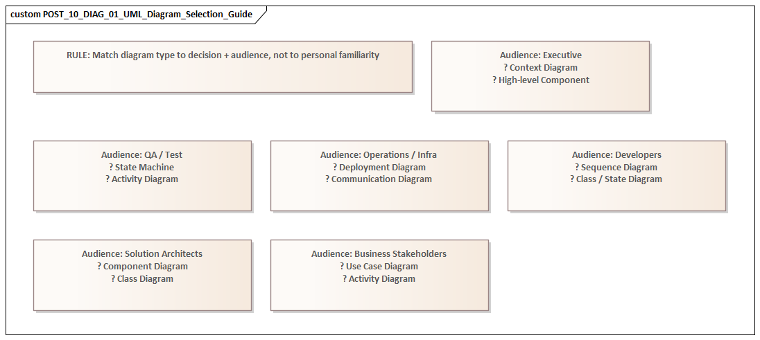
One of the most common enterprise modeling mistakes is selecting a UML diagram because it is familiar rather than because it fits the problem. Teams may know how to draw several diagram types, yet still be unclear about when each one is actually useful. The result is predictable: a single diagram gets stretched beyond its natural role. Sequence diagrams become process maps, class diagrams become logical data models, component diagrams become application landscapes, and use case diagrams turn into functional specifications.
This is where the principle from the introduction becomes practical. A diagram should support a specific decision for a specific audience. Different stakeholders need different views. Business stakeholders may want to understand scope and actor interaction. Solution architects may need service responsibilities and interface boundaries. Operations teams may care about runtime placement, failover assumptions, and network dependencies. Force one diagram to answer all of those questions and it usually answers none of them well.
Typical examples
Use case diagrams are often overloaded with implementation detail, exception handling, and internal orchestration. That weakens the very thing they are good at: defining scope, actors, and the externally visible services a system provides. Once the conversation moves into sequencing or branching behavior, an activity or sequence diagram is usually the better choice.
Component diagrams are frequently used to represent anything modular: applications, products, APIs, services, platforms, or infrastructure. Without a clear purpose, the same box ends up meaning different things to different readers. A component diagram should primarily show structural decomposition and interfaces. If the real goal is enterprise portfolio mapping, another view is usually better. If the goal is runtime topology, a deployment diagram is the better fit. In an IAM modernization, for example, a component diagram can clarify identity provider, policy decision point, directory, and application integration responsibilities; it should not be stretched into a complete migration roadmap or operating model.
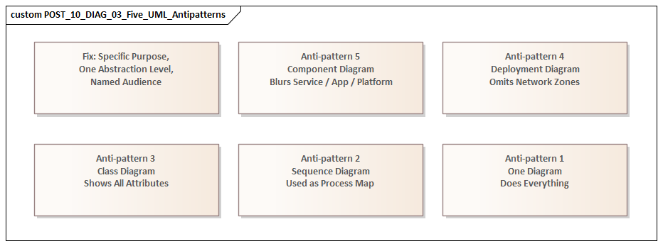
Sequence diagrams are excellent for showing time-ordered interactions and the flow of responsibility. They become far less useful when treated as general integration documentation. Once every alternate path, business rule, and exception is packed into one view, the result is too dense for review and still too incomplete for implementation. In an event-driven architecture using Kafka, a sequence diagram can show producer, topic, consumer, and error-handling responsibilities for a single business event; it should not try to represent the entire event estate.
Why it matters in enterprise projects
Using the wrong diagram type does more than make documentation untidy. It pushes the conversation in the wrong direction. One stakeholder may think scope has been agreed when the team is really discussing process flow. Another may assume a deployment decision has been made when the diagram only shows logical structure. In large programs, that sort of confusion leads directly to governance friction and delivery misalignment.
A realistic example is an ERP integration program where a component diagram was used to brief infrastructure teams on runtime design. The diagram showed finance services, middleware, and reporting components, but nothing about network zones, region placement, or failover dependencies. Infrastructure teams inferred a hosting model that had never been agreed. The correction came late, after firewall requests and environment sizing had already been based on the wrong assumptions.
Better practice
Start with the question, not the notation. Before drawing anything, ask:
- Are we clarifying scope, structure, behavior, or deployment?
- Who is this diagram for?
- What decision should it support?
That discipline reduces the urge to overload a single artifact and produces a cleaner set of views. It also helps reveal when multiple diagrams are needed rather than one overworked diagram that tries to do everything.
2. Overmodeling with Excessive Detail
Once teams choose a diagram, many swing to the opposite extreme: they try to include everything. The result is overmodeling—diagrams so crowded they stop functioning as architecture and start reading like fragile design inventories. how architecture review boards use Sparx EA
UML is useful when it improves decision quality. Too much detail does the opposite. It buries the architectural point under attributes, branches, exceptions, utility components, and connector lines. A reviewer should be able to spot key boundaries, dependencies, and risks quickly. If a diagram takes sustained effort just to decode, it is no longer doing its job.
How overmodeling appears
- Class diagrams include low-value attributes and methods that belong in code or detailed design.
- Sequence diagrams attempt to capture every branch, retry, validation rule, and error state in one place.
- Component diagrams show internal libraries and helper utilities when the real issue is service ownership or interface exposure.
- Activity diagrams become long operational narratives that duplicate procedure manuals.
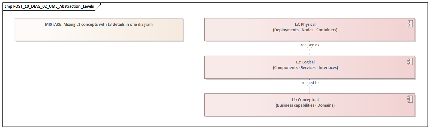
The problem is not that the details are incorrect. The problem is that they are shown at the wrong level for the audience and the decision at hand.
Why it is especially harmful in enterprise settings
Enterprise architecture depends on selective abstraction. Its role is not to document everything; it is to highlight what matters for coordination, governance, and risk. When everything receives equal visual weight, the important and the incidental blur together. A major trust boundary can disappear in a web of arrows. A critical external dependency can be lost among routine internal interactions.
There is also a maintenance problem. Highly detailed diagrams age quickly. As systems change, those details go stale faster than high-level architectural intent. Once stakeholders notice that diagrams no longer match reality, confidence in the repository starts to erode.
This happens often in regulated environments. A payments team may produce a sequence diagram showing tokenization steps, fraud checks, retries, timeout handling, settlement branching, and support desk escalation in one image. The intent is completeness. The effect is the opposite. Reviewers cannot quickly tell where card data crosses trust boundaries, which call is synchronous, or where compensating controls apply. The diagram contains more information, but less usable meaning.
Better practice
Model by question, not by completeness. If the question is integration risk, show the systems, contracts, and interaction patterns that affect that risk. If the question is security design, show identity flow, trust zones, and control points. If the question is team coordination, show ownership boundaries and dependencies.
For example, in IAM modernization, a sequence diagram showing token issuance, policy evaluation, and privileged access checks is usually more useful than a single diagram containing every authentication variant. In a customer onboarding platform, a component view that distinguishes onboarding portal, KYC service, document store, and case management interfaces is more useful to a review board than a detailed decomposition of internal validation libraries.
A practical rule helps: if an element does not help a stakeholder make a decision, identify a risk, or understand a boundary, it probably does not belong in that diagram.
The discipline to leave detail out is just as important as the ability to add it. That becomes even more important when multiple teams are modeling related parts of the same solution.
3. Creating Contradictory Models Across Teams
In large enterprise programs, the biggest UML problems often do not sit inside a single diagram. They show up across a collection of diagrams produced by different teams. One view treats a system as external while another shows it as internal. One sequence model shows synchronous interaction; another implies event-driven behavior. One team models a capability as shared platform infrastructure, while another treats it as a project-owned service.
These are not just documentation defects. They usually point to unresolved architecture.
Why this happens
Enterprise modeling is distributed by nature. Business analysts model scope. Solution architects model services and interfaces. Infrastructure teams model deployment. Vendors bring their own design packs. Without shared conventions and review discipline, these views drift. Sparx EA training
The problem becomes even more likely when the first two mistakes are already in play:
- teams use diagrams for unclear purposes,
- and they include too much local detail.
When each team brings its own style, abstraction level, and terminology, the repository stops being a coherent architecture and becomes a collection of local truths.
Why consistency matters
Structural, behavioral, and deployment models do not need to be identical, but they do need to be compatible. If a component exposes an interface in one view, that interface should appear consistently in the relevant interaction models. If a deployment view places workloads in a restricted network zone, sequence diagrams should not imply unrestricted direct access. If ownership changes from one diagram to another, governance decisions about funding, support, and change control become unreliable.
These inconsistencies also create delivery risk. Developers may build to one interaction pattern while operations prepares for another. Security teams may assess controls against a topology that no longer matches the interaction design. Testing teams may derive scenarios from assumptions that conflict with responsibilities shown elsewhere. A common example is Kafka adoption: one team’s component model shows asynchronous publication through shared topics, while another team’s sequence view still assumes point-to-point synchronous calls.
A familiar micro-example appears in data platforms. A central architecture team may model the “Customer Master” as an enterprise service owned by the data platform team. Meanwhile, a CRM delivery team models the same capability as an internal application component under its own change control. The contradiction is not cosmetic. It affects funding, release sequencing, support ownership, and incident escalation.
Better practice
Consistency does not require one giant model. It requires a controlled baseline. Core concepts should be defined once and reused:
- system boundaries,
- service names,
- actors,
- environments,
- interface types,
- ownership,
- and key terms such as component, application, platform, and external system.
A lightweight glossary or modeling meta-model is often more useful than producing more diagrams.
Review discipline matters just as much as standards. Rather than reviewing each artifact in isolation, review related views together:
- Do interfaces match across structural and behavioral views?
- Do actors align with business scope?
- Do deployment assumptions support the interaction model?
- Are ownership boundaries stable across artifacts?
Cross-view review often exposes unresolved design issues early. If one view still assumes direct database access while another shows only API-mediated access, the team has found an architecture decision that is not actually closed.
That kind of coherence depends on clear notation, which leads to the next mistake.
4. Misusing Relationships and UML Semantics
Even when teams choose the right diagram and keep it at the right level, they can still mislead readers by using notation loosely. In enterprise UML, relationships, multiplicities, dependency arrows, aggregations, compositions, and interface markers are often used in ways that look reasonable but communicate the wrong meaning.
Because UML appears formal, readers tend to assume the semantics are deliberate. That makes misuse especially risky.
Common problems
Generic “related to” lines
Many diagrams use simple associations to mean almost anything: structural linkage, API usage, ownership, data synchronization, inheritance, or runtime interaction. In enterprise settings, that ambiguity gets expensive quickly. One team reads the line as a service dependency, another as data flow, and a third as an organizational relationship.
Misused aggregation and composition
Filled and hollow diamonds are often added to make diagrams look more rigorous, even when no real whole-part lifecycle dependency exists. Composition is a strong statement: the part is owned by the whole and usually cannot exist independently. If a shared database or shared service is shown that way, readers may draw the wrong conclusions about ownership and replaceability.
Missing or misleading multiplicity
Multiplicity is often omitted when it matters, or added mechanically when it does not. Yet in enterprise design, cardinality can reveal assumptions about tenancy, sharing, contention, and scaling. A one-to-one relationship may hide a multi-tenant reality. A one-to-many relationship may imply shared access patterns with security implications.
Incorrect directionality
Arrows are sometimes drawn for layout convenience rather than semantic accuracy. In architecture, direction shapes dependency analysis, coupling assessment, migration planning, and change impact. Reverse a dependency arrow and the apparent control structure of the system may be completely wrong.
Why this matters
Cross-team consistency depends not only on shared terminology but also on shared semantics. If one team uses arrows to mean runtime calls and another uses them to mean compile-time dependency, the models may look aligned while saying different things. The same issue appears in technology lifecycle governance when a dependency arrow is mistaken for a hosting relationship and the impact of retiring a product version is assessed incorrectly.
Consider a realistic example from a data retention program. A component diagram showed an archive service connected to three business applications with undirected lines. Compliance stakeholders read that as data being pushed into the archive by the applications. Operations interpreted the same lines as the archive service pulling records on a schedule. Security assumed a shared access relationship. Three different readings came from one ambiguous notation choice.
Better practice
Treat notation as a precision tool, not decoration.
- Use a relationship only when its meaning is clear.
- Use composition and aggregation sparingly, and only when lifecycle dependency truly matters.
- Include multiplicity when scale or cardinality affects architecture.
- Leave out formal detail when it does not matter, rather than implying false precision.
- If you use local conventions, explain them explicitly.
In enterprise modeling, semantic discipline is what turns diagrams into reliable tools for reasoning rather than pictures open to interpretation.
Clear semantics also make it easier to connect technical structure back to business purpose, which is where many UML models still fall short.
5. Ignoring Business Context
A UML diagram can be technically correct and still weak from an architectural point of view if it is detached from business context. This is a common enterprise failure. Teams model services, interfaces, components, and deployment nodes with care, but never make clear why those elements matter, which business capability they support, or what operational outcome depends on them.
The result is a model that is structurally sound but poor at supporting decisions.
What gets lost
When UML is treated as purely technical documentation, models often leave out:
- business capabilities,
- domain ownership,
- regulatory or policy drivers,
- service-level expectations,
- customer impact,
- operational consequence,
- and value-critical paths.
As a result, architecture discussions focus on how the solution is built rather than whether it supports the enterprise objective.
Why this creates risk
Without business context, prioritization weakens. Every component looks equally important. Teams struggle to justify resilience investment, migration sequencing, or control design because the diagrams do not distinguish critical functions from supporting ones.
Accountability becomes blurred as well. If systems are modeled without business ownership or domain boundaries, it becomes harder to determine who funds change, accepts risk, or governs service quality.
Architecture assurance suffers too. A review board may see a technically coherent design and still lack the context needed to judge strategic fit. For instance, an architecture board deciding whether to modernize IAM first for workforce access or customer identity needs models that show affected business capabilities, risk exposure, and operational impact, not just protocol flows.
This is especially visible in operational workflows. A sequence diagram may correctly show calls between order capture, inventory, payments, and dispatch services, yet say nothing about the fact that dispatch failure affects same-day delivery commitments in premium markets. Without that context, latency and resilience discussions remain abstract when they should be commercially grounded.
Where this appears
Use case and activity models are especially vulnerable. Teams often describe system interactions without showing the business event, policy trigger, or value exchange that gives those interactions meaning. A workflow may be drawn accurately, yet the model says nothing about whether the control exists for compliance, financial authorization, customer safety, or internal delegation.
Sequence diagrams can suffer from the same problem. They may show service calls correctly while hiding the customer impact of latency, failure, or manual intervention.
Better practice
UML becomes valuable when it supports real decisions. In enterprise work, those decisions are rarely purely technical. Models should connect technical structure to business intent.
That does not mean every UML diagram has to become a business architecture artifact. It means the model should make clear:
- what capability or process is in scope,
- which actors or business roles are affected,
- which policies or outcomes matter,
- and where the operational or commercial consequence sits.
Simple additions go a long way:
- name components by business responsibility, not only by platform label;
- identify actors in operational terms;
- annotate critical paths with service-level expectations;
- link interactions to business events or control points.
When UML shows both technical design and business consequence, it becomes much more useful to mixed stakeholder groups.
That usefulness, however, depends on whether the model remains trustworthy over time.
6. Failing to Govern and Evolve Models
Even a well-structured UML model becomes a liability if nobody maintains it. In enterprise environments, this is one of the most underestimated failures. Teams put real effort into diagrams for funding approval or architecture review, then treat them as static deliverables. Once implementation starts, the models drift away from reality.
Why this is dangerous
An outdated UML model does more than reduce documentation quality. It leads people to make decisions based on false assumptions. A sequence diagram may still show direct integration even after an event broker has been introduced. A deployment view may show single-region runtime after resilience design changed the topology. A component model may preserve old ownership boundaries after services were reassigned.
This gets worse when the earlier mistakes are already present:
- overmodeled diagrams become obsolete quickly,
- contradictory diagrams make it hard to tell which one is current,
- and weak semantics make drift harder to detect.
In one platform rationalization effort, a target-state component diagram continued to show a legacy document management product as the system of record six months after ownership had moved to a SaaS platform. Downstream teams kept designing integrations against the old interface because the architecture repository still treated the obsolete diagram as authoritative. The problem was not the original model; it was the absence of lifecycle discipline.
Root causes
Most organizations define templates for creating UML artifacts, but not for governing them over time. Diagrams accumulate in repositories with unclear status:
- draft,
- approved baseline,
- historical snapshot,
- current state,
- transition state,
- or target state.
When that status is not explicit, readers are left to guess which model is authoritative.
There is also a transition-state problem. Enterprise transformation rarely happens in one move. Legacy and target systems often coexist. Interim interfaces appear. Security controls are staged. UML models frequently fail because they show only an idealized future state or a simplified current state, but not the governed path between them. This is especially visible in technology lifecycle governance, where a target-state diagram may show a strategic platform while omitting the still-supported legacy product versions that drive upgrade risk and exception approvals.
Better practice
Treat important UML artifacts as managed architectural assets.
Each significant model should have:
- an owner,
- a defined purpose,
- a status,
- a review cadence,
- and a clear relationship to change control.
Changes to interfaces, deployment topology, trust boundaries, or service ownership should trigger a review of affected diagrams. Where possible, connect UML artifacts to architecture repositories, API catalogs, CMDBs, or delivery workflows so they are less likely to drift in isolation.
It also helps to define retirement rules. Some diagrams are temporary decision records and should be archived when superseded. Others are enduring reference views and should remain current because multiple teams depend on them. A practical example is lifecycle governance: when a database platform moves from tolerated to sunset, the supporting deployment and dependency views should be updated as part of the governance action, not months later.
Governance is what turns UML from a one-time approval artifact into a durable architecture tool.
A Practical Checklist for Better Enterprise UML
The pattern across these mistakes is straightforward: UML fails when teams model without enough clarity about purpose, abstraction, semantics, and lifecycle. A lightweight checklist can prevent many of the problems described above. fixing Sparx EA performance problems
Before publishing a UML diagram, ask:
Purpose and audience
- What architectural question does this diagram answer?
- Who is expected to read it?
- What decision should it support?
Scope and abstraction
- Is the diagram at the right level for that audience?
- Does it show only the elements needed for the decision?
- Are important omissions intentional?
Viewpoint alignment
- Does it align with other relevant diagrams?
- Are names, boundaries, interfaces, and ownership consistent?
- Would another team interpret the model the same way?
Notation discipline
- Are relationships semantically clear?
- Are arrows, multiplicities, and ownership markers accurate?
- Have local conventions been explained?
Business relevance
- Does the diagram show the business capability, role, event, or outcome in scope?
- Can a non-technical stakeholder understand why the design matters?
- Are critical paths, controls, or service expectations visible where relevant?
Governance and lifecycle
- Is the model current, transitional, or target state?
- Who owns it?
- When will it be reviewed or retired?
This checklist does not require heavyweight modeling governance. It simply reinforces the core idea introduced at the start of the article: UML is most useful when every view has a purpose, a defined audience, and a decision to support.
Conclusion
UML becomes valuable in enterprise projects only when it is used as a disciplined architectural language rather than as a documentation habit. The most serious mistakes are rarely isolated notation errors. They arise when teams choose the wrong view, overload diagrams with detail, let models contradict each other, use notation ambiguously, detach technical structure from business purpose, or allow models to drift out of date.
All of these failures reduce trust. In enterprise architecture, trust is the real currency of a model. A diagram must be clear enough to support discussion, precise enough to avoid false interpretation, and current enough to guide real decisions. Sparx EA guide
The central principle is simple: every UML diagram should have a clear purpose, a defined audience, and an explicit decision it is meant to support. That principle helps teams choose the right diagram type, control detail, align views across workstreams, use notation carefully, connect design to business context, and govern models over time.
Used that way, UML is not just a set of pictures attached to design documents. It becomes a curated set of decision-oriented views that improve alignment, assurance, and controlled change across the enterprise. That is the standard worth aiming for: not more diagrams, but more useful ones.
Frequently Asked Questions
What are the most common UML modeling mistakes in enterprise projects?
The most common mistakes are: using the wrong diagram type for the audience (e.g. sequence diagrams in executive reviews), mixing abstraction levels within a single diagram, over-specifying implementation detail in structural diagrams, omitting multiplicities and relationship semantics, and producing diagrams that are visually polished but answer the wrong architectural question.
How do you choose the right UML diagram for enterprise architecture?
Match diagram type to decision purpose: Component diagrams for application structure and ownership, Deployment diagrams for infrastructure topology and resilience, Sequence diagrams for runtime interaction and failure handling, Class diagrams for domain models and data contracts, and Use Case diagrams for functional scope and stakeholder alignment.
Why do UML diagrams lose value in large enterprise programs?
UML diagrams lose value when they are not maintained after initial creation, are inconsistently scoped across teams, mix concerns from different abstraction levels, or are produced primarily for compliance rather than communication. Regular governance reviews and explicit diagram fitness criteria help maintain quality across large programs.