⏱ 26 min read
UML Modeling for Microservices Architecture: Diagrams, Patterns, and Best Practices Sparx EA training
Learn how UML modeling supports microservices architecture with practical diagrams, design patterns, and best practices for scalable, maintainable distributed systems. Sparx EA best practices
UML modeling, microservices architecture, UML for microservices, software architecture diagrams, microservices design, UML diagrams, system design, distributed systems, architecture patterns, service modeling, sequence diagrams, component diagrams, deployment diagrams, scalable architecture, technical architecture how architecture review boards use Sparx EA
Introduction
Microservices architecture is now a standard choice for enterprise systems that must evolve quickly, scale unevenly, and support delivery across multiple teams. Splitting a platform into services aligned to business capabilities can improve agility, localize change, and reduce the blast radius of failure. It also introduces a different class of complexity. As services, APIs, event streams, data stores, runtime platforms, and operational dependencies multiply, teams need a reliable way to understand the system beyond the boundaries of a single codebase. UML still serves that purpose well because it provides a disciplined visual language for reasoning about distributed architecture.
In a microservices environment, UML is most effective when used as lightweight architecture modeling rather than exhaustive design documentation. The point is not to capture every class, endpoint, or implementation detail. The point is to make architectural decisions visible: where service boundaries sit, how services collaborate, which data each service owns, what infrastructure they rely on, and where security or operational constraints shape the design. In enterprise settings, that visibility matters even more because services rarely operate in isolation. They interact with API gateways, identity providers, event brokers such as Kafka, observability stacks, cloud services, and legacy platforms that often introduce coupling in less obvious ways.
That distinction is important because microservices frequently appear more independent than they are. A service may be isolated in source control while still depending on a shared database, a tightly coupled downstream call chain, centralized authentication, or common operational tooling. UML helps expose those dependencies early. A component diagram can show ownership boundaries and interfaces. A sequence diagram can reveal latency-sensitive call paths or hidden orchestration. A deployment diagram can make trust zones, runtime topology, and shared infrastructure explicit. Taken together, these views help architects assess whether a design is genuinely decoupled, resilient, and governable.
Different stakeholders also need different architectural views. Product and business leaders care about capability boundaries and workflow impact. Developers need clarity on contracts and interaction patterns. Platform and operations teams need to understand runtime dependencies, resilience assumptions, and infrastructure placement. Architecture boards need enough evidence to decide, for example, whether a new notification capability belongs inside an existing customer platform or should be established as a separate service. UML supports those perspectives without forcing every concern into one overloaded picture.
The value comes from modeling with intent. Teams should capture the views that help with design reviews, governance, onboarding, modernization planning, and incident analysis, and no more. Used in that way, UML is not just a communication aid. It becomes a practical decision tool that helps manage microservices complexity without sacrificing the autonomy and speed that make the style attractive in the first place.
Foundations of UML in Microservices Architecture
Applying UML to microservices starts with selective abstraction. The aim is not to model every endpoint, class, or infrastructure detail, but to represent the elements that materially affect architecture decisions. In practice, that usually includes business capabilities, service responsibilities, interfaces, data ownership, interaction style, and deployment relationships.
A useful starting point is to treat each microservice as an architectural unit with explicit boundaries. In UML, that usually means modeling a service as a component with defined provided and required interfaces. This reinforces a core principle: a microservice is defined less by its internal implementation than by the contracts it exposes and the dependencies it consumes. Making interfaces explicit helps teams separate stable contracts from internal design choices, which is essential if services are to evolve independently.
A second foundation is viewpoint separation. No single diagram can explain a microservices architecture. Different concerns belong in different views:
- Structural views explain service decomposition, interfaces, and dependencies.
- Behavioral views explain runtime collaboration, sequencing, and workflow.
- Deployment views explain runtime placement, trust boundaries, and infrastructure assumptions.
Confusion usually starts when teams try to combine all of that into a single diagram. Effective UML use depends on choosing the view that matches the question being asked.
Bounded context thinking should also shape the model. Service boundaries should reflect coherent business responsibilities and ownership of data and rules, not technical layers or team convenience. A strong model makes clear what a service owns, which interactions cross context boundaries, and where translation or orchestration is required. Many microservices problems come not from the number of services, but from weak partitioning that creates chatty communication, duplicated logic, or shared persistence.
It is equally important to model interaction style, not just connectivity. A line between two services says very little unless the nature of the dependency is clear. Is it synchronous or asynchronous? Request-response or event-driven? Does the caller depend on immediate downstream availability? Those distinctions affect latency, failure propagation, and consistency, so they should be visible. In an IAM modernization program, for example, a UML model should distinguish between services that still make direct LDAP lookups and those that authenticate through centralized OIDC token validation. Both may appear to “depend on identity,” but the architecture consequences are very different.
Finally, UML is most useful when tied to architectural intent. A diagram should show not only what is connected, but why the structure exists. If a service is isolated to protect sensitive data, reduce blast radius, or support independent scaling, that rationale should be captured through annotations or linked decisions. That turns UML from static description into a decision-support artifact, which is where it delivers the most value in enterprise microservices architecture.
Core Microservices Concepts and Architectural Boundaries
Microservices boundaries are business decisions before they are technical ones. A microservice should represent a capability that can be owned, changed, deployed, and operated with minimal dependence on unrelated parts of the system. UML is useful here because it makes those boundaries visible and open to scrutiny instead of leaving them implicit.
A central distinction is between functional decomposition and real autonomy. A system can be split into dozens of small services and still behave like a distributed monolith if those services must change together, share databases, or participate in tightly coupled call chains. For that reason, the goal of modeling is not to maximize service count. The goal is to expose coupling. A good structural model should make it possible to ask:
- Can this service be versioned independently?
- Can it fail without collapsing the entire business flow?
- Does it own its data and rules?
- Can another team understand its purpose without tracing several other services first?
Data ownership is one of the clearest indicators of a healthy boundary. Each service should be the authoritative owner of its own data and business rules within its scope. Microservices often appear independent while persistence remains shared underneath. UML can make that visible by associating each service with its own store and showing other services interacting only through APIs or events. This is not just cleaner documentation. It reveals whether the architecture supports independent evolution or merely hides coupling in the database layer.
Consider a retail example. An Order Service may expose order status through an API, while a Customer Service needs that information for account history screens. If the Customer Service reads directly from the order schema for convenience, the architecture has already compromised the boundary. A component diagram that shows Customer Service consuming an order query API or subscribing to OrderCompleted events makes the intended ownership explicit and gives reviewers something concrete to challenge.
Another key concept is the balance between orchestration and choreography. Some business processes need a central coordinator to manage workflow steps, policy checks, and compensations. Others work better as event-driven collaboration, where services react independently to domain events. UML helps teams decide which style fits a scenario by showing where process control sits, which services understand the broader workflow, and where temporal coupling exists. Too much orchestration can create a process hub that owns too much business logic. Too much choreography can make end-to-end behavior opaque.
A realistic pattern appears in order management. An OrderPlaced event may be published to Kafka and consumed by payment, inventory, and notification services independently. That works well when each service can act on the event within its own boundary. By contrast, a claims process in insurance may require a dedicated workflow service because approvals, fraud checks, and manual interventions must be coordinated and audited in a defined sequence. Both patterns are valid, but they should not look identical in the model.
Boundaries also need to reflect operational reality. Two capabilities may be closely related in business terms and still deserve separate services because they scale differently, carry different compliance requirements, or are maintained by different teams. Conversely, splitting a stable capability into multiple services may add operational overhead with little gain in autonomy. UML should therefore capture not only domain relationships, but also trust zones, scaling hotspots, externally exposed interfaces, and dependencies on specialized infrastructure.
Boundary erosion over time is another practical concern. Initial designs often look clean, but delivery pressure introduces convenience integrations, shared libraries with embedded domain logic, or synchronous shortcuts that bypass intended contracts. Once an earlier boundary model exists, UML becomes a governance aid because it makes those deviations visible during review. If one service starts depending on another service’s private schema, internal event format, or internal object model, the diagram should expose that as an architectural smell rather than allowing it to disappear into implementation detail.
Ultimately, microservices architecture is about preserving clarity of responsibility in a distributed system. UML supports that by showing what a service owns, how it communicates, what it depends on, and where its responsibilities end.
Applying UML Structural Diagrams to Microservices Design
Once boundaries are established, structural UML diagrams provide the baseline map of the system. They show what exists, what depends on what, and where architectural constraints need to be enforced. In microservices architecture, that static view matters because many risks come from the shape of the dependency network itself.
Component Diagrams
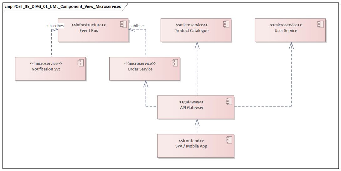
The most useful structural view for microservices is usually the component diagram. Each microservice can be modeled as a component with provided and required interfaces. That makes contracts visible in a way that simple boxes-and-lines sketches usually do not.
For example, a service may:
- provide a REST or gRPC API,
- publish domain events,
- consume commands or events from other services,
- depend on identity, messaging, or configuration services.
Representing these separately helps architects distinguish inbound from outbound dependencies and identify services that are quietly becoming coordination hubs.
Component diagrams are also the right place to include platform elements that materially shape behavior, such as:
- API gateways,
- identity providers,
- service discovery,
- message brokers,
- configuration services,
- observability platforms.
Services are rarely autonomous in purely technical terms. In practice, many depend heavily on shared platform layers. Making those dependencies visible gives a more realistic view of resilience and governance. An architecture board may, for instance, approve a standard pattern in which all internet-facing services authenticate through a shared IAM platform and expose APIs only through the enterprise gateway, while rejecting service-specific login implementations embedded inside business services.
A realistic micro-example is a digital banking platform where the Account Service provides balance and transaction APIs, publishes AccountOverdrawn events, and requires token introspection from a central identity service. On paper, the service appears self-contained. In the component diagram, however, reviewers can immediately see that customer-facing availability also depends on the API gateway, the IAM platform, and the event broker used for downstream alerts.
Package Diagrams
For larger environments, package diagrams help show domain partitioning above the level of individual services. Packages can represent bounded contexts, business domains, or capability groups, with services organized inside them. This is especially useful when the main challenge is not understanding one service, but understanding how dozens of services relate to the enterprise operating model.
This view supports questions such as:
- Which domains are tightly connected?
- Where are cross-domain dependencies legitimate?
- Where do those dependencies suggest poor decomposition?
- How does service ownership align with business capability structure?
Package diagrams are particularly useful for modernization planning, team topology discussions, and portfolio-level architecture reviews. They also help with technology lifecycle governance. A package view can quickly show, for example, that several services in the pricing domain still depend on a deprecated gateway product or an aging Java runtime, making remediation planning easier to prioritize.
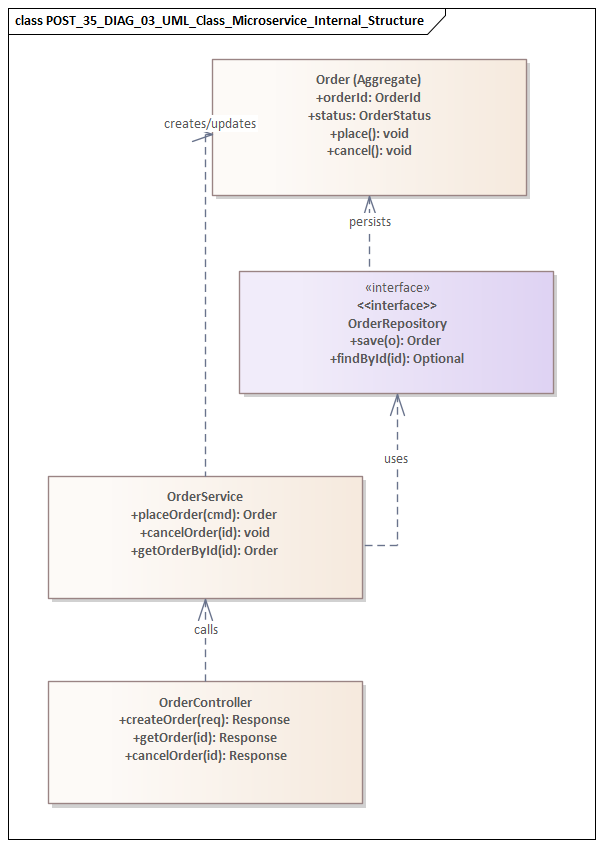
Class Diagrams
The class diagram has a narrower role in microservices architecture. It is usually not appropriate to model the full internal object structure of every service at the architecture level. Even so, class diagrams can be useful at integration boundaries for:
- shared domain vocabularies,
- canonical event structures,
- API resource models,
- anti-corruption mappings between legacy and microservice domains.
Used selectively, they help teams align on semantics without dragging architecture discussions into implementation detail. This is particularly helpful when legacy systems are involved. A modernization team may use a class diagram to show how a mainframe “customer account” record maps to a more explicit domain model split across Customer, Account, and Billing services. That level of modeling clarifies boundary translation without requiring a full design model for each service.
Exposing Hidden Coupling
Structural diagrams are especially valuable for identifying undesirable coupling patterns. Common examples include:
- multiple services depending on the same database schema,
- cross-service joins through a shared reporting store,
- common internal libraries that embed business rules,
- “hub” services that accumulate too many required interfaces.
These patterns often explain why a supposedly modular microservices estate still requires coordinated releases or suffers from fragile change management.
To make structural diagrams more useful, add light annotations for dependency type, ownership, and criticality. A line alone is rarely enough. Mark whether a dependency is synchronous or asynchronous, internal or externally exposed, and whether it is compliance-sensitive or operationally critical. A small amount of precision turns a static picture into a design and governance tool.
Using UML Behavioral Diagrams to Model Service Interactions
If structural diagrams explain the shape of the architecture, behavioral diagrams show how it behaves at runtime. This is where interaction style, orchestration versus choreography, and service autonomy become concrete. In microservices, runtime behavior often determines whether a design is robust or fragile.
Sequence Diagrams
The most directly useful behavioral tool is the sequence diagram. It models end-to-end scenarios such as order placement, customer onboarding, or claim submission by showing which service initiates each step, which interactions are synchronous, and when control returns to the caller.
That matters because sequence diagrams can reveal issues that structural views alone may miss:
- long latency-sensitive call chains,
- unnecessary synchronous dependencies,
- hidden orchestration in nominally thin services,
- retry amplification and cascading failure risk.
For customer-facing flows, a sequence diagram quickly shows whether the user request depends on too many downstream services to meet performance and reliability expectations. fixing Sparx EA performance problems
Sequence diagrams are also valuable for hybrid interaction models. Many enterprise processes combine synchronous API calls with asynchronous events, background processing, and callbacks. If that mix is not modeled explicitly, teams often assume a stronger level of consistency than the architecture can actually provide. Showing asynchronous messages, time gaps, and alternate paths helps distinguish between immediate transaction completion and eventual business completion.
A common example is checkout. The Checkout API may synchronously validate the cart, reserve payment authorization, and persist the order, then publish an OrderAccepted event to Kafka. Fulfillment, fraud screening, and customer notification proceed asynchronously. If the sequence diagram shows only a neat linear flow, stakeholders may assume that shipment and confirmation are complete when the API returns. A more accurate model prevents that misunderstanding and prompts better discussion about user messaging, SLAs, and recovery behavior.
Activity Diagrams
Activity diagrams are useful for business workflows that span multiple services and decision points. They are especially effective when the process includes branching logic, parallel execution, approvals, compensating actions, or handoffs between automated and human-driven work.
This view is helpful for answering questions such as:
- Does the workflow require a central process manager?
- Can parts of the process run in parallel?
- Where are policy decisions made?
- Which steps are architecturally significant for compliance or audit?
This is often where the trade-off between orchestration and choreography becomes easiest to see. In a loan approval process, for example, credit scoring, identity verification, and fraud checks may run in parallel, while final approval remains a controlled decision point. An activity diagram makes that split visible and helps prevent the accidental concentration of all logic inside a single orchestration service.
State Machine Diagrams
For state-sensitive domains, state machine diagrams add another important perspective. Some services manage entities whose lifecycle is central to business correctness, such as orders, subscriptions, shipments, or support cases. Modeling state transitions helps teams reason about:
- valid and invalid events,
- authorization requirements for transitions,
- duplicate message handling,
- retries, compensations, and terminal states.
These diagrams are particularly useful in event-driven systems, where messages may arrive out of order or more than once. A clear state model helps architects validate idempotency and recovery behavior instead of leaving it implicit.
A practical example is a Subscription Service with states such as PendingActivation, Active, Suspended, Cancelled, and Expired. Without a state model, teams may overlook whether a duplicate PaymentReceived event can reactivate a cancelled subscription or whether customer support is allowed to move directly from suspended to expired. A state machine exposes those rules early, before they emerge as production defects.
Modeling Failure Behavior
Behavioral diagrams should not show only the happy path. In distributed systems, architecturally significant failure modes include:
- timeouts,
- unavailable dependencies,
- duplicate events,
- partial completion,
- compensating actions,
- escalation to manual handling.
The point is not to document every technical exception. It is to show the failure paths that materially affect business outcomes. A review is much stronger when teams can see not only how a process succeeds, but also how it degrades and recovers.
Used well, behavioral UML validates service interaction design. It helps teams test whether responsibilities sit in the right place, whether process control is too centralized, and whether asynchronous communication is being used deliberately rather than by accident.
Modeling Deployment, Infrastructure, and Operational Concerns
The earlier sections establish service boundaries and runtime behavior. In microservices, though, the architecture is incomplete until it is mapped to the environment where it runs. Deployment-oriented UML makes operational assumptions visible: where services run, what infrastructure they depend on, how traffic flows, and where trust boundaries are enforced.
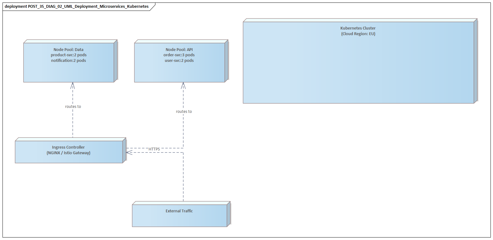
Deployment Diagrams
The primary UML tool here is the deployment diagram. In a microservices context, it can show nodes such as:
- Kubernetes clusters,
- virtual machines,
- cloud regions and availability zones,
- edge gateways,
- managed databases,
- message brokers,
- external SaaS services.
Services are then mapped onto those nodes so runtime placement becomes explicit.
This matters because deployment topology has architectural consequences. Two services may appear loosely coupled in a component diagram and still share operational fate if they depend on the same cluster, ingress controller, secrets manager, or regional database endpoint.
A concrete example is a healthcare platform where Patient Service and Appointment Service are modeled as separate components with distinct databases. The deployment diagram may reveal that both run in the same cluster, depend on the same service mesh control plane, and use a shared managed PostgreSQL instance in one region. That does not invalidate the logical separation, but it does change the conversation about resilience, maintenance windows, and compliance isolation.
Environment Separation
A good deployment model should also show environment separation. Development, test, staging, and production often differ in topology, controls, and integrations. Lower environments may use mocks, shared infrastructure, or simplified security flows, while production depends on hardened identity, dedicated networking, and audited data access.
Representing those differences helps avoid a common problem: diagrams that imply a simpler runtime model than the one actually used in production. It also helps explain why a service that works cleanly in test may fail in production under stricter network policy, certificate rotation, or token validation rules.
Trust Boundaries and Network Zones
Deployment views should also capture network and trust boundaries. Not every connection is equally permitted or trusted. Relevant zones may include:
- public ingress,
- internal service networks,
- restricted data domains,
- partner integration segments,
- administrative control planes.
This lets architects show where TLS terminates, where mutual authentication is required, where traffic passes through gateways or service meshes, and which services may communicate directly. In regulated environments, these views are often essential for security review. They are also useful during IAM modernization, for example when documenting the move from application-managed credentials to centralized OIDC tokens, policy enforcement, and service-to-service authentication.
Operational Platform Dependencies
Platform components are part of the architecture, not background detail. Deployment models should include operational dependencies such as:
- logging and metrics pipelines,
- distributed tracing,
- alerting platforms,
- certificate managers,
- secret stores,
- policy engines,
- CI/CD agents or deployment controllers.
A service may only be deployable if sidecars are injected, startup configuration is retrieved, and telemetry is exported. Leaving out those dependencies can make the architecture look far simpler than it really is.
Resilience and Scaling Assumptions
Deployment diagrams are also useful for testing resilience and scaling assumptions. Annotate where relevant:
- replication and load balancing,
- single-zone or multi-zone placement,
- active-active versus active-passive patterns,
- dependencies on stateful storage,
- failover arrangements,
- infrastructure single points of failure.
This helps validate whether the service autonomy described in earlier sections is matched by operational independence.
Deployment UML should not try to duplicate cloud configuration or automation templates. Its purpose is to make operationally significant relationships visible so teams can support production readiness reviews, disaster recovery planning, compliance assessment, and platform strategy decisions. free Sparx EA maturity assessment
Governance, Documentation, and UML Best Practices for Enterprise Microservices
Once the core views are defined, the next challenge is keeping them useful. In enterprise environments, architectural knowledge tends to fragment across wikis, ticket systems, service catalogs, and API portals. UML adds value only when it is managed as a living architectural asset rather than isolated design artwork.
A practical governance approach is to define which UML views are required for which kinds of decisions. Not every service needs the same level of modeling. A lightweight internal utility may need only a component view and a deployment reference. A customer-critical domain service may also require sequence diagrams for key journeys, state models for lifecycle-sensitive entities, and deployment views showing resilience and trust boundaries.
This tiered approach works better than a uniform documentation standard because it aligns modeling effort with:
- business criticality,
- change impact,
- integration complexity,
- regulatory or operational risk.
UML artifacts should also be linked to related architecture assets. A diagram explains structure, but not always intent. To preserve the reasoning behind it, connect UML views to:
- architecture decision records,
- service catalog entries,
- API specifications,
- event schemas,
- ownership and support metadata.
This creates traceability between what was designed, why it was designed that way, and who is responsible for evolving it.
Consistency matters as well. Enterprises should define a small notation guide for microservices UML usage, including conventions for: Sparx EA guide
- synchronous versus asynchronous interactions,
- externally exposed services,
- data ownership,
- deprecated dependencies,
- platform services versus business services.
Without these conventions, models from different teams become difficult to compare and govern.
Most importantly, UML should be maintained continuously. In fast-moving microservices estates, diagrams become misleading if they are updated only during initial design or formal review. Architectural changes that should trigger model review include:
- new service dependencies,
- interface or event contract changes,
- shifts in communication style,
- deployment topology changes,
- trust boundary or compliance changes,
- domain boundary adjustments.
That does not mean every sprint requires diagram updates. It means any architecturally meaningful change should update the representation of the architecture.
Governance should also use UML to detect drift and policy exceptions. Over time, teams may introduce direct point-to-point integrations, bypass approved messaging patterns, or depend on shared stores for convenience. These decisions may not be obvious from local code review alone. UML-based review checkpoints help surface divergence from intended architecture principles before it becomes systemic. A technology lifecycle review may use package and deployment diagrams to identify services still running on a database version scheduled for retirement, while an architecture board may use the same models to require a migration plan before approving new feature investment.
In practice, the best UML usage optimizes for communication and stewardship, not completeness. A good model is one that helps teams evaluate change, govern complexity, and understand responsibility boundaries with minimal ambiguity.
Common Pitfalls, Anti-Patterns, and Practical Adoption Strategies
Even with good intentions, UML modeling for microservices can fail if it becomes ceremonial, misleading, or disconnected from delivery. Several pitfalls recur in enterprise environments.
One common problem is false architectural confidence. Teams may produce polished diagrams that suggest clean service separation while the real system still depends on shared schemas, coordinated releases, or undocumented operational workarounds. A diagram that hides inconvenient realities is worse than no diagram at all because it creates the illusion of control.
Another frequent issue is the wrong abstraction level. Some models are so high-level that they show only service names and arrows, offering little insight into interaction style, criticality, or hidden coupling. Others are overloaded with implementation detail and become unreadable outside the immediate team. The useful middle ground is enough detail to expose architectural risk without turning the model into a maintenance burden.
A related anti-pattern is modeling the org chart instead of the architecture. Services may be grouped by reporting line or funding boundary while actual runtime dependencies remain obscured. Ownership should be visible, but it should not replace architectural truth. A service boundary justified only by team structure is not necessarily a sound microservices boundary.
Another pitfall is static documentation. UML often gets produced for design approval and then left untouched while interfaces, event contracts, deployment paths, and resilience patterns evolve. Over time, the repository may look complete but cannot be trusted during modernization planning, incident response, or integration design. The issue is not UML itself; it is the lack of a maintenance model.
Teams also frequently under-model platform influence. Service meshes, gateways, identity flows, CI/CD controls, quotas, and observability standards often shape the architecture as much as domain decomposition does. Leaving them out of UML produces designs that may be logically elegant but operationally unrealistic.
Practical Adoption Strategies
The most effective adoption approach is incremental. Start with a small set of high-value views tied to real decisions. For architecturally significant services, that usually means:
- One structural view showing boundaries, interfaces, and key dependencies.
- One interaction view for a critical business scenario.
- One deployment view where runtime topology, trust, or resilience matters.
This creates a practical baseline without overwhelming delivery teams.
A second strategy is to integrate modeling into existing workflows rather than treating it as separate documentation work. UML updates should be triggered by changes such as:
- new dependencies,
- new externally exposed interfaces,
- changes from synchronous to asynchronous interaction,
- topology or trust-boundary changes,
- significant resilience or compliance changes.
Linking this to architecture reviews, ADR updates, onboarding, and service catalog processes makes UML part of normal engineering governance.
It also helps to start where pain already exists. If a platform suffers recurring incidents caused by hidden dependencies, begin with sequence and deployment diagrams for those flows. If modernization is blocked by unclear domain ownership, start with package and component views. If compliance review repeatedly uncovers undocumented trust paths, make deployment diagrams mandatory for regulated services. Adoption is stronger when teams see UML solving a real problem rather than satisfying a general documentation requirement.
Finally, teams need to understand that the goal is not comprehensive modeling. The goal is to make visible the aspects of the architecture most likely to create enterprise risk if they remain implicit. Used that way, UML helps organizations detect drift early, challenge optimistic assumptions, and evolve distributed systems with greater clarity and control.
Conclusion
UML remains valuable in microservices architecture because distributed systems require clear architectural reasoning, not simply more diagrams. As microservices estates grow, the real challenge is maintaining a shared understanding of boundaries, dependencies, interaction patterns, and operational consequences across many teams. UML supports that understanding when it is used selectively and tied to real decisions.
Its strongest role is as a living representation of architectural intent. Structural views show service boundaries and dependencies. Behavioral views show how collaboration unfolds at runtime. Deployment views show where resilience, trust, and platform dependence shape production reality. Together, these models make it easier to test whether the architecture is genuinely autonomous, governable, and aligned with business needs.
Just as importantly, UML supports architectural accountability. When service contracts, workflows, and deployment assumptions are visible, design trade-offs become easier to review and challenge. That is especially important in enterprise modernization, where cloud-native services, legacy systems, shared IAM platforms, event backbones such as Kafka, and technology lifecycle constraints must coexist for long periods.
Used with discipline, UML is not a legacy documentation exercise. It is a practical way to keep complex microservices landscapes understandable, governable, and capable of controlled evolution.
Frequently Asked Questions
What UML diagram types are most useful for enterprise architects?
For enterprise architecture: Component diagrams (application structure and interfaces), Deployment diagrams (infrastructure topology), Sequence diagrams (runtime interactions), Class diagrams (domain models and data structures), and Use Case diagrams (functional scope). Each serves a different audience and purpose.
What are the most common UML modeling mistakes?
Common mistakes include: using the wrong diagram type for the audience, mixing abstraction levels in a single diagram, over-specifying implementation detail in structural diagrams, omitting multiplicities and relationship types, and creating diagrams that are not navigable or meaningful outside their original context.
How does UML relate to ArchiMate in enterprise architecture?
UML and ArchiMate are complementary. ArchiMate is used for enterprise-wide architecture across business, application, and technology layers. UML is used for software design — class structures, sequences, components, and deployments within a single application or domain. In Sparx EA, both notations coexist in the same repository.