⏱ 31 min read
Introduction: The Architecture Imperative
The telecommunications industry is undergoing a structural transformation more profound than any it has experienced since the shift from circuit-switched to packet-switched networks. The simultaneous arrival of 5G commercial deployment, cloud-native infrastructure, open API ecosystems, AI-driven network operations, and real-time data monetisation is not a collection of independent technology waves — it is a single, compounding disruption that touches every layer of the operating model simultaneously. enterprise cloud architecture patterns
Operators that approach this transition one domain at a time — upgrading the OSS here, replacing the billing system there, bolting on a Kubernetes cluster elsewhere — will find themselves perpetually behind, perpetually integrating, and perpetually explaining to the board why the transformation programme is over budget and under-delivered. The root cause is almost always the same: the absence of a coherent, cross-cutting Enterprise Architecture that connects strategic intent to delivery reality.
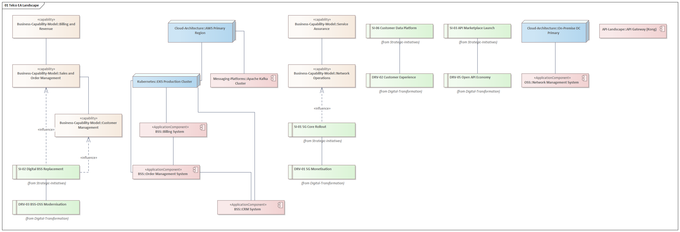
This article presents a complete, practitioner-grade Telco Enterprise Architecture repository, built in Sparx Enterprise Architect using ArchiMate 3.1 notation and aligned throughout with TM Forum's eTOM B18 process framework and SID R18 information model. Every diagram was generated from a single automated JScript, producing a living model that spans eleven architecture domains — from governance and strategy through capabilities, applications, infrastructure, integration, security, and roadmaps — with full cross-domain traceability.
We walk through every layer, explain the design decisions, and show the actual Sparx EA diagrams that were produced. By the end, you will have a complete reference architecture you can adapt for your own operator context. Sparx EA best practices
Governance and EA Principles
Every EA programme lives or dies by its governance model. Without a clear set of principles, a functioning Architecture Review Board, and an enforced standards catalogue, an EA repository is just a collection of diagrams that drifts out of date the moment it is published.
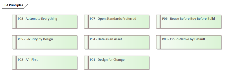
The governance layer of this architecture defines eight foundational principles that constrain and guide every decision made across all other domains. These are not aspirational statements — they are binding design rules that translate directly into Architecture Decision Records and, from there, into technology choices.
- P01 — Design for Change: Every component must be replaceable without architectural surgery. This principle drives the preference for loosely coupled microservices, event-driven integration, and contract-first API design.
- P02 — API-First: No capability is exposed without a formally versioned API contract. This directly motivates the mandatory adoption of TM Forum Open APIs (ADR-003).
- P03 — Cloud-Native by Default: New workloads run on Kubernetes unless there is a documented exception. This principle is realised by ADR-002 (Kubernetes for all workloads) and the GitOps deployment mandate (ADR-006).
- P04 — Data as an Asset: All data has a named owner, a classification, a retention policy, and a canonical representation in the CDM. This drives the EU-only data residency decision (ADR-009) and the entire data governance framework.
- P05 — Security by Design: Security controls are not bolted on after delivery — they are architectural constraints from the first design review. This realises ADR-007 (OAuth 2.0 / OIDC for all authentication) and ADR-010 (Zero Trust as default).
- P06 — Reuse Before Buy Before Build: Capabilities are sourced from existing internal assets first, then from market solutions, and only built bespoke when neither alternative exists. This drives the Solution Building Block library.
- P07 — Open Standards Preferred: Proprietary vendor-specific protocols and data formats are rejected in favour of TMF, 3GPP, CloudEvents, and IETF standards. Vendor lock-in is an architectural defect.
- P08 — Automate Everything: Manual processes in deployment, testing, compliance reporting, and network operations are treated as technical debt. This principle motivates the AIOps programme, GitOps deployment, and the CI/CD pipeline SBB.
The Architecture Review Board (ARB) is the governance mechanism that ensures these principles are applied consistently. It operates as a formal review gate for all significant architectural decisions — new system selections, major integration changes, platform migrations, and security policy updates. The ARB is chaired by the Chief Enterprise Architect and includes Domain Architects for BSS/OSS and Network, plus the Security Architect as a permanent member.
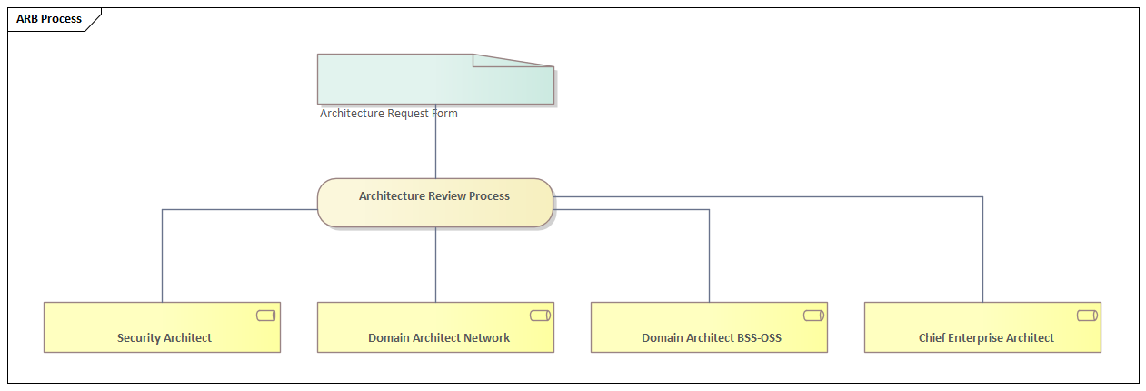
The ARB is not a bottleneck — it is an accelerator. When teams know that their design will be reviewed against the eight principles and the ADR register, they front-load the architectural thinking rather than discovering compliance failures in delivery. Done well, the ARB reduces rework, not agility.
Strategy Layer: Drivers and Initiatives
The strategy layer answers the question: why are we doing any of this? It connects the external pressures the organisation faces to the internal programmes it will run in response. Without this layer, an EA repository is a technical artefact disconnected from business intent — and it will be ignored by the C-suite accordingly.
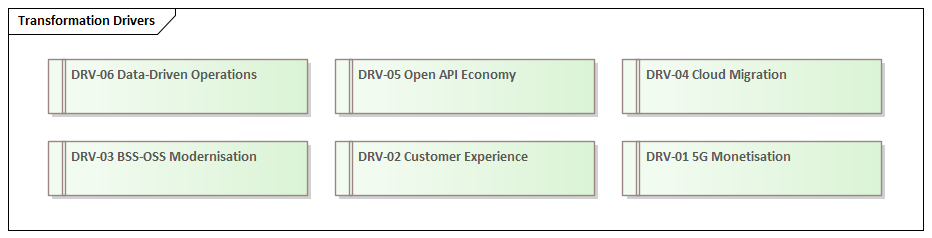
Six transformation drivers define the external and internal forces shaping the architecture over the next three years:
- DRV-01 — 5G Monetisation: The capital investment in 5G infrastructure must generate revenue from enterprise customers, IoT, and network-as-a-service propositions. This is not just a network programme — it requires BSS, product management, and API platform capabilities to be rebuilt simultaneously.
- DRV-02 — Customer Experience: NPS scores and churn rates are directly correlated with the quality of self-service capabilities and the speed of issue resolution. Legacy BSS systems with batch-overnight processing cycles are architecturally incompatible with the real-time experience customers now expect.
- DRV-03 — BSS/OSS Modernisation: The majority of incumbent operators run billing, ordering, and provisioning systems that are fifteen to twenty years old. The cost of maintaining these systems — in licence fees, integration complexity, and change lead times — now exceeds the cost of replacement.
- DRV-04 — Cloud Migration: Public cloud provides elastic capacity, managed services, and a consumption-based cost model that fixed on-premise infrastructure cannot match. The architectural challenge is migrating stateful, latency-sensitive telco workloads without compromising SLAs.
- DRV-05 — Open API Economy: TM Forum's Open Gateway initiative and the CAMARA project are creating a global marketplace for telco capabilities exposed as standard APIs. Operators that publish well-governed APIs can monetise their network investments through a developer ecosystem — but only if their internal architecture can support it.
- DRV-06 — Data-Driven Operations: AI and machine learning applied to network telemetry, customer behaviour, and operational data can reduce OPEX by 20–30% through predictive maintenance, intelligent routing, and automated root cause analysis. This requires a modern data platform and a governance framework that makes data trustworthy enough to feed models.
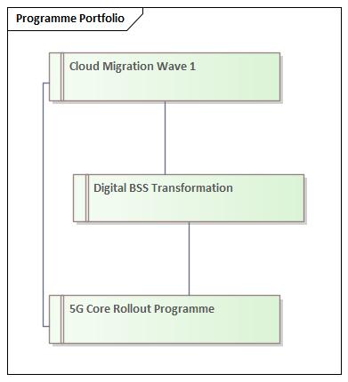
Each driver motivates one or more strategic initiatives. The six initiatives in the repository represent the major transformation programmes the operator will run over a three-year horizon:
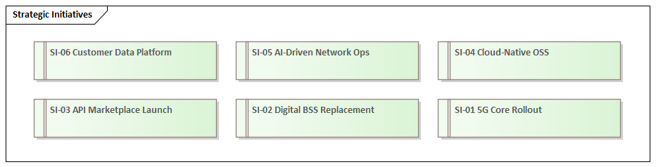
The critical architectural discipline here is traceability. Every strategic initiative must connect forward to capabilities (what business capability is being enhanced?), application systems (which systems will be replaced or built?), and roadmap milestones (when will the value be delivered?). If you cannot draw that line, the initiative is a budget request, not an architecture-informed decision.
Business Architecture: Capabilities, Processes and Journeys
The business architecture layer translates strategic intent into operational structure. It defines what the organisation needs to be able to do (capabilities), how those activities are sequenced (value streams and processes), what it sells (products), how customers experience it (journeys), and how it is organised to deliver (organisation structure).
Business Capability Map
The capability map is the cornerstone of the business architecture. It defines twelve level-one capabilities, each representing a distinct area of business functionality that the organisation must possess regardless of which systems implement it or how the organisation is structured. Capabilities are stable — they change far more slowly than processes, applications, or organisation charts, which makes them the ideal anchor for architectural planning.
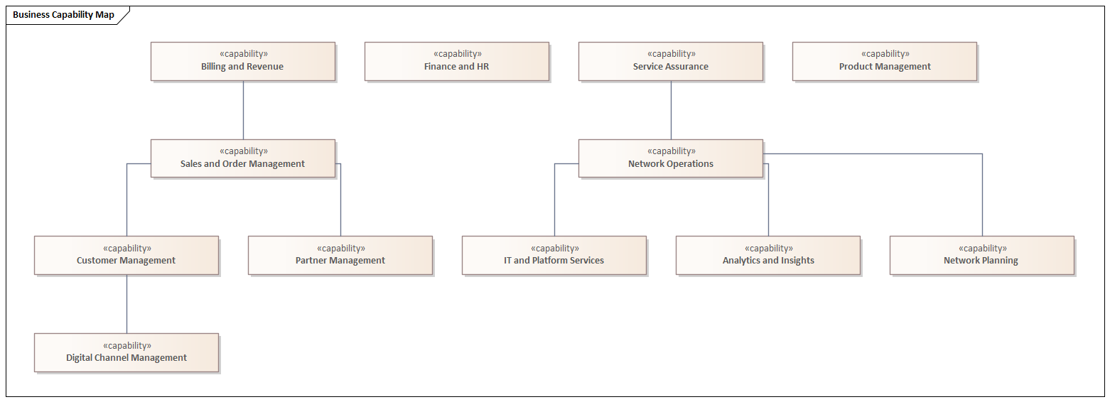
The capability map serves three strategic purposes. First, it provides a common vocabulary — when the CTO says “we need to improve our order management capability,” the EA model defines precisely what that means and which systems, processes, and people are involved. Second, it enables heat-mapping: overlaying capability maturity scores, investment levels, or strategic importance ratings to identify where gaps and over-investments exist. Third, it anchors the gap analysis that drives the application roadmap — every application in the landscape can be mapped to one or more capabilities, and every capability gap justifies an investment. ArchiMate for governance
Value Streams
Six value streams represent the cross-functional flows through which the operator creates and delivers value to its customers and stakeholders. Unlike processes, value streams are defined from the outside in — from the customer or stakeholder perspective rather than from the internal organisational view.
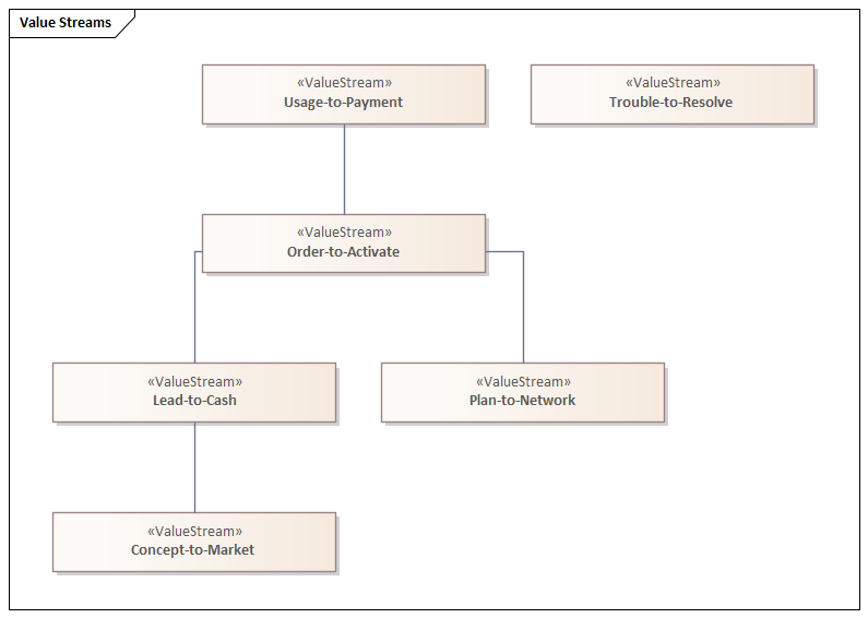
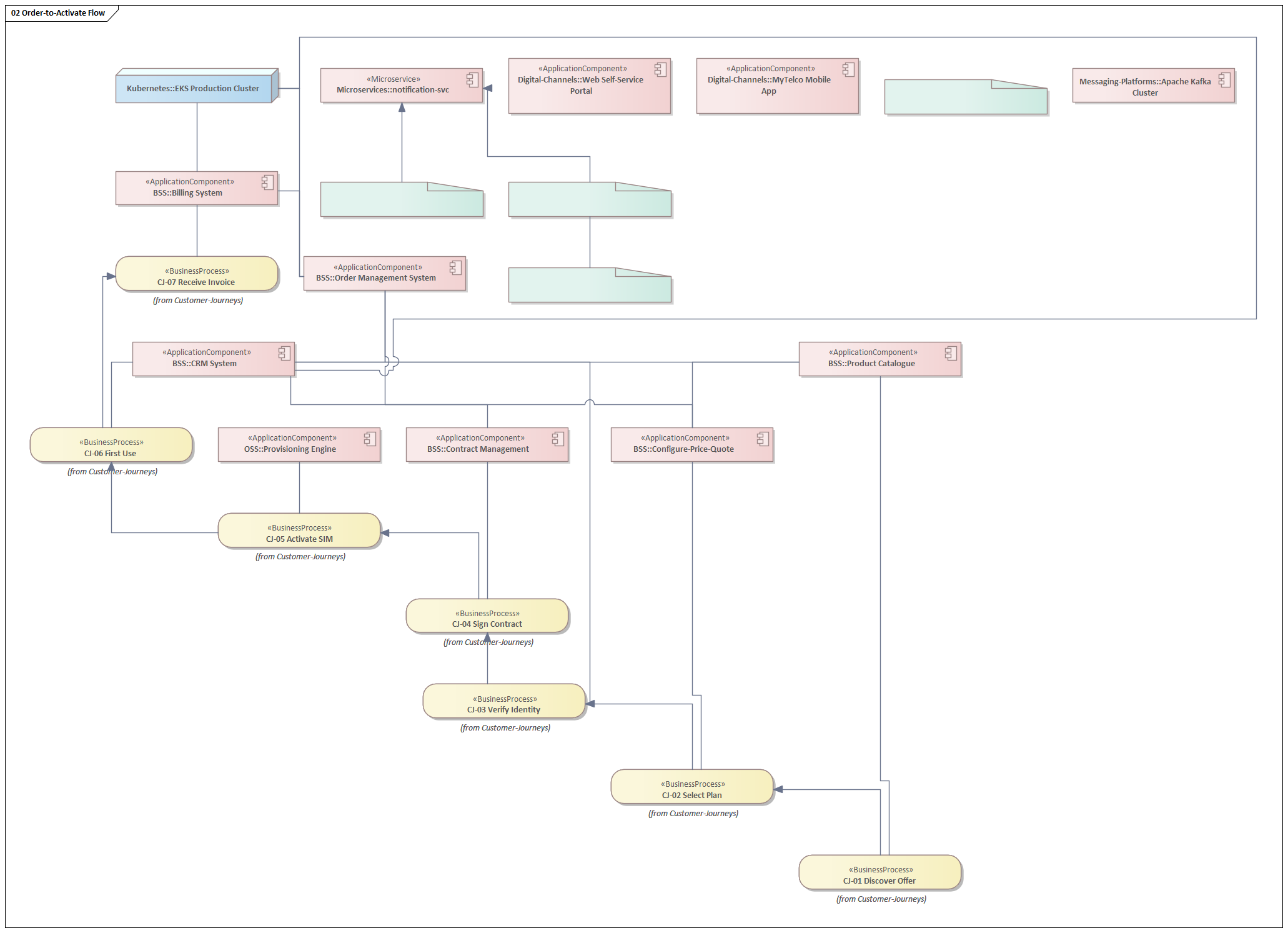
Lead-to-Cash encompasses everything from the first marketing touchpoint through contract signature. Order-to-Activate covers the fulfilment journey from order placement to service activation — the value stream with the most complex cross-system dependencies and the highest customer satisfaction impact. Trouble-to-Resolve drives NPS more than almost any other stream; a customer who has a problem resolved quickly and transparently is more loyal than one who never had a problem. Usage-to-Payment is the revenue engine — mediation, rating, and billing. Plan-to-Network represents the capacity and coverage planning cycle that underpins service quality. Concept-to-Market covers the product development and launch cycle.
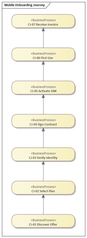
Customer Journey: Mobile Onboarding
The customer journey model zooms in to the individual experience level. The Mobile Onboarding Journey captures the seven steps a new customer passes through from discovering an offer to receiving their first invoice — each step mapped to the applications and processes that support it.
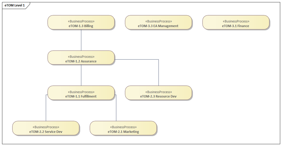
eTOM Process Framework
The TM Forum enhanced Telecom Operations Map (eTOM) is the industry-standard process framework for telecommunications operators. The architecture aligns all business processes to eTOM Level 1 (the Operational, Strategy/Infrastructure/Product, and Enterprise domains) and decomposes selected critical processes to Level 2.
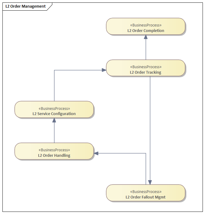
The Level 2 decomposition of Order Management illustrates how high-level capability flows into granular, executable process steps — Order Handling, Service Configuration, Order Tracking, Order Completion, and Order Fallout Management — with explicit triggering relationships that can be traced directly to microservice orchestration design.
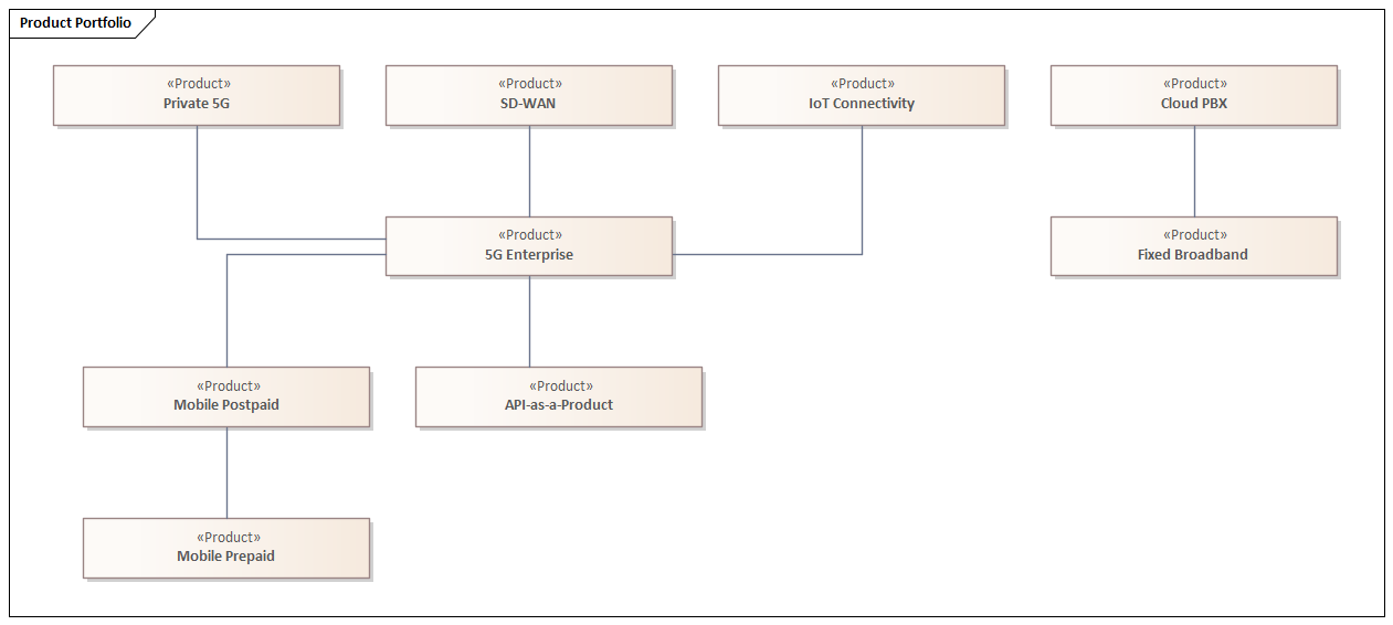
Product Portfolio
The product portfolio model captures the operator’s commercial offer structure. Nine products span Consumer (Mobile Postpaid, Mobile Prepaid, Fixed Broadband) and Enterprise (5G Enterprise, IoT Connectivity, Cloud PBX, SD-WAN, Private 5G) segments, plus the strategic API-as-a-Product offering that enables third-party monetisation of network capabilities.
Information Architecture: CDM and Data Governance
Bad data is the silent killer of digital transformation programmes. Operators attempting to provide real-time personalised experiences, predictive network operations, or trusted AI-driven decisions cannot do so when the same customer exists as seventeen different records across nine systems, when “product” means something different in the CRM, the catalogue, and the billing system, and when nobody owns the definition of “active subscriber.”
The information architecture layer addresses this through a Canonical Data Model (CDM) aligned to TM Forum’s SID R18, a Master Data Management strategy, and a formal Data Governance framework.
Canonical Data Model
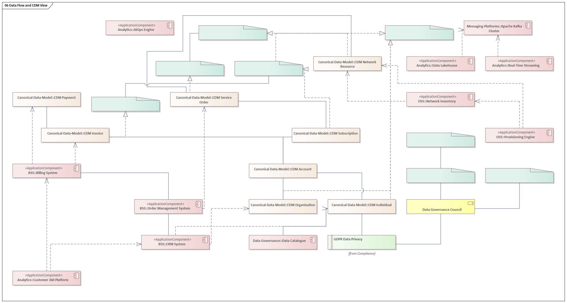
The CDM defines eleven core business entities and their relationships. It is the authoritative reference that all systems must conform to when exchanging data — not a physical schema, but a logical contract that governs integration.
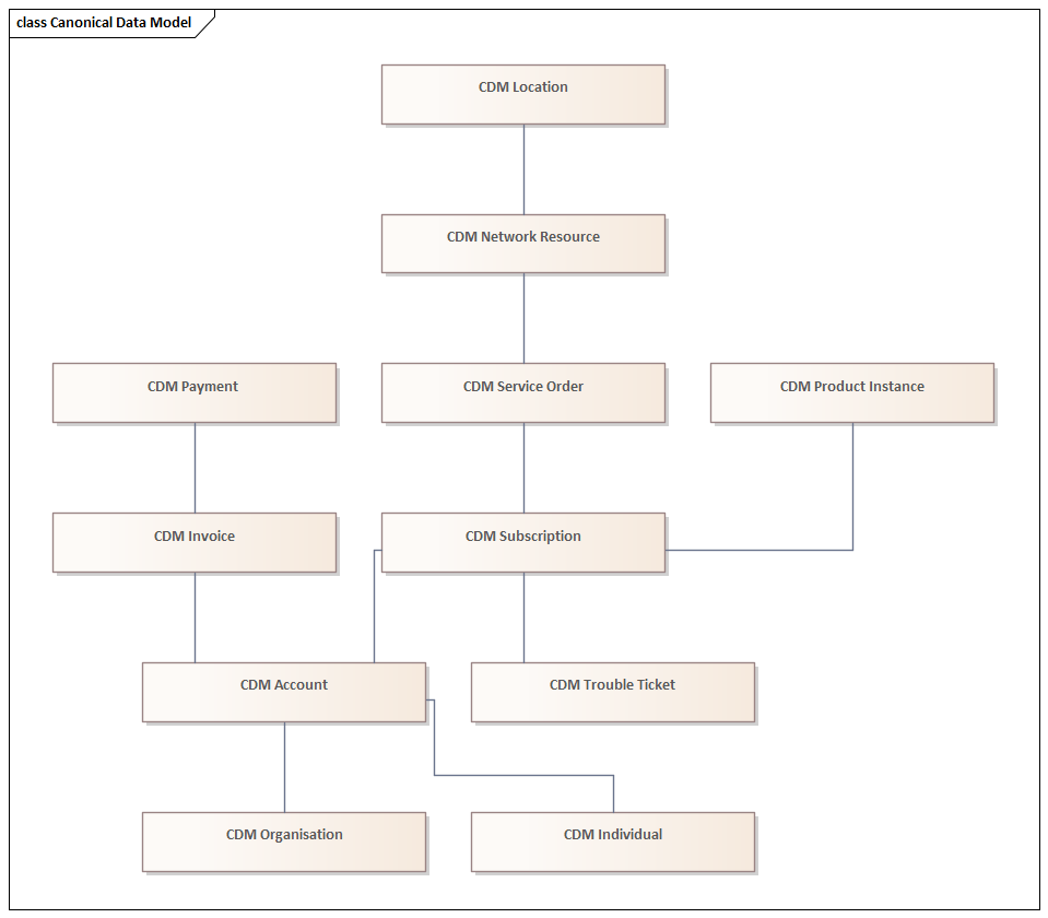
The CDM is structured around a customer-centric hierarchy: an Individual or Organisation holds one or more Accounts. Each Account has one or more Subscriptions, which instantiate Product Instances and generate Service Orders. Service Orders allocate Network Resources at a Location. The Account produces Invoices that are settled by Payments. Problems are captured as Trouble Tickets against Subscriptions.
Every CDM entity is explicitly mapped to its corresponding TM Forum SID Aggregate Business Entity (ABE). Individual and Organisation realise SID Party. Subscription realises SID Customer. Service Order realises SID Service. Network Resource realises SID Resource. Invoice realises SID Revenue. This alignment is not cosmetic — it ensures that any TM Forum Open API integration can be mapped directly to the CDM without a bespoke translation layer.
Data Governance
Data governance defines the roles, policies, and tools that make the CDM trustworthy at runtime. Without governance, a canonical model is a document that nobody enforces.
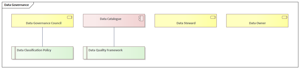
The Data Governance Council owns the CDM and arbitrates disputes about entity definitions. Data Owners are senior business stakeholders accountable for the quality of specific master data domains (Customer MDM, Product MDM, Network Resource MDM, Location MDM, Employee MDM, Partner MDM). Data Stewards are operational roles responsible for the day-to-day quality of specific entities within those domains. The Data Catalogue (realised by a technology tool such as Apache Atlas or Collibra) is the operational registry that exposes these definitions and lineage to data consumers across the organisation.
Application Architecture: BSS, OSS and Microservices
The application architecture layer defines the systems that implement the business capabilities. It is structured across five domains: Business Support Systems (BSS), Operations Support Systems (OSS), Digital Channels, Analytics, and the microservices layer that increasingly provides the implementation fabric for all of them.
BSS Landscape
The BSS domain covers the customer-facing and commercial back-office systems. The architecture defines nine BSS applications, each mapped to one or more business capabilities and connected through explicit dependency relationships.
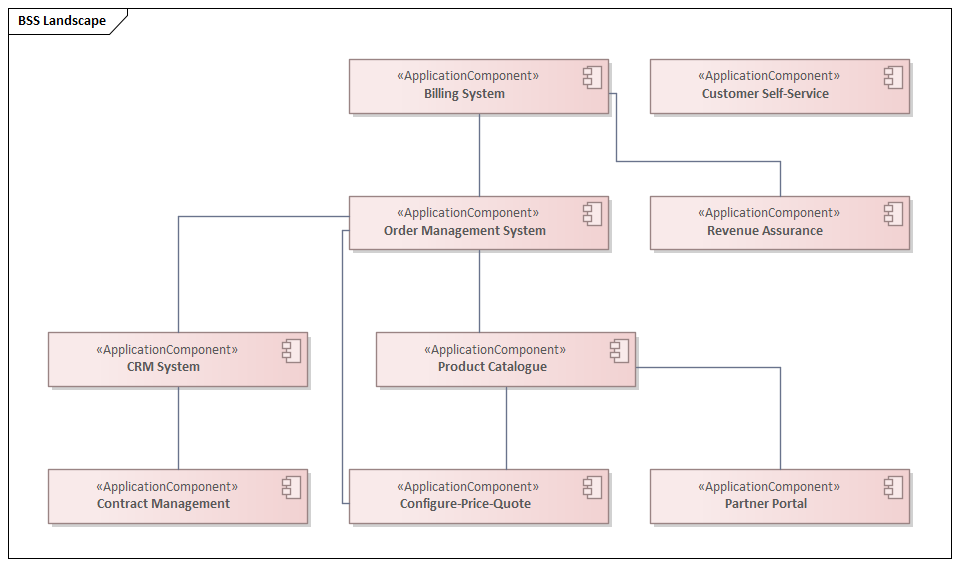
The CRM System is the system of record for customer identity and relationship history. The Product Catalogue is the authoritative source of offer definitions that flows downstream into Configure-Price-Quote, Order Management, and ultimately Billing. The Order Management System is the orchestration hub of the fulfilment value stream — it receives orders from the CRM and digital channels, decomposes them into service and resource orders, and coordinates their execution across OSS systems. The Billing System closes the commercial loop, translating usage records and one-time charges into invoices and managing collections.
OSS Landscape
The OSS domain manages the network and service infrastructure that delivers the products the BSS systems sell. The architecture defines eight OSS applications across inventory, management, assurance, and provisioning functions.
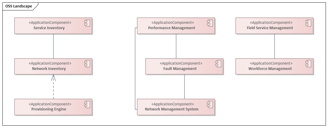
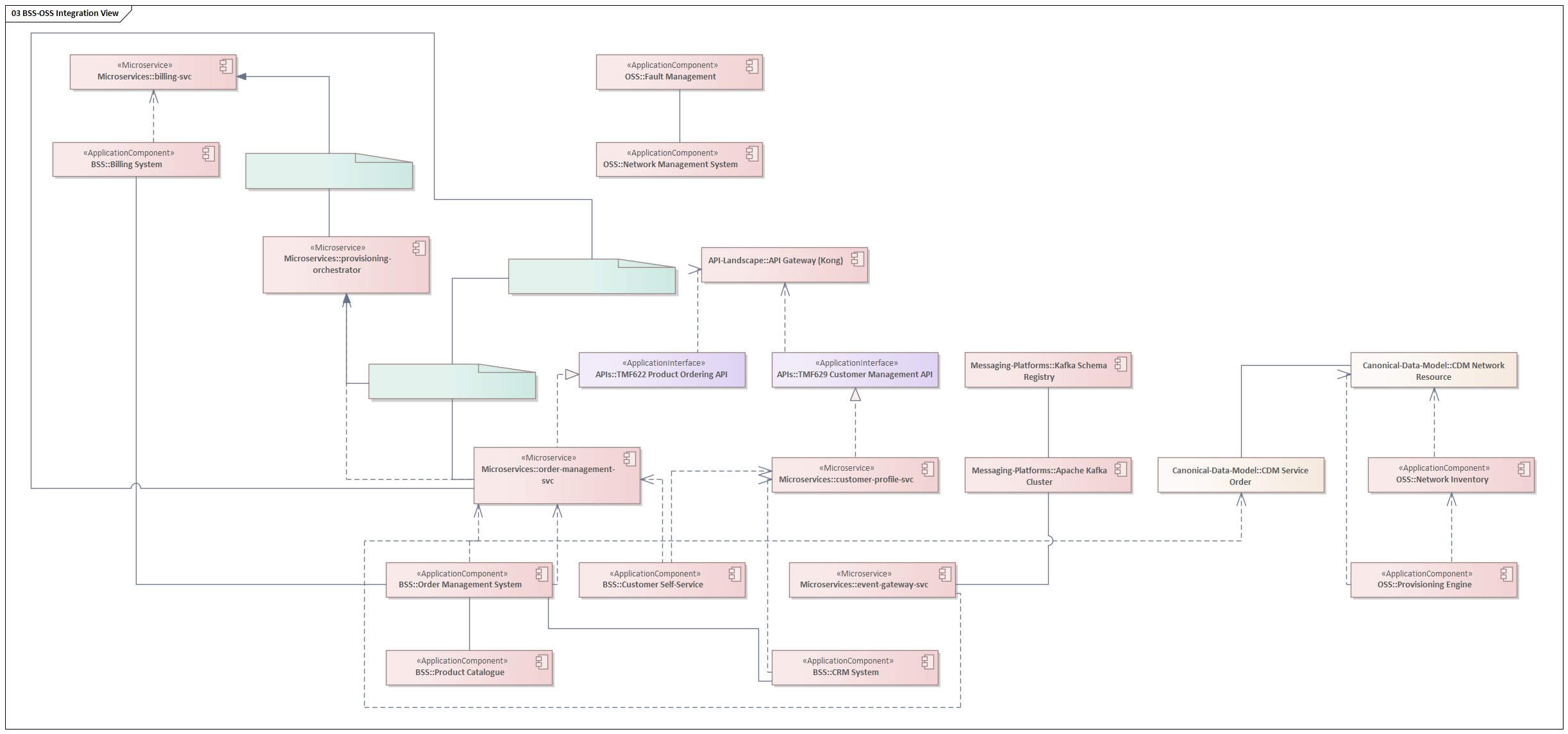
The Provisioning Engine is the critical integration point between BSS and OSS — it receives service activation instructions from the Order Management System (via the TMF641 Service Order API) and translates them into network configuration commands. Network Inventory and Service Inventory provide the source-of-truth for what exists in the network, which the Provisioning Engine must query and update with every change. Fault Management and Performance Management feed the AIOps Engine with the operational telemetry that drives predictive maintenance.
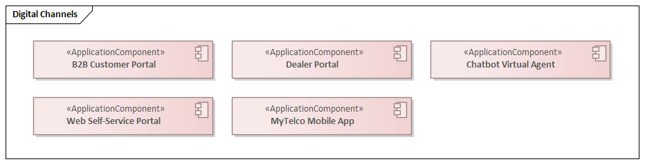
Digital Channels
Core Microservices
The microservices layer represents the target-state implementation architecture for the BSS domain. Rather than large monolithic applications communicating through direct database integration, the target architecture decomposes capabilities into ten fine-grained services, each owning its own data, exposing a versioned API contract, and communicating asynchronously through events where coupling must be minimised.
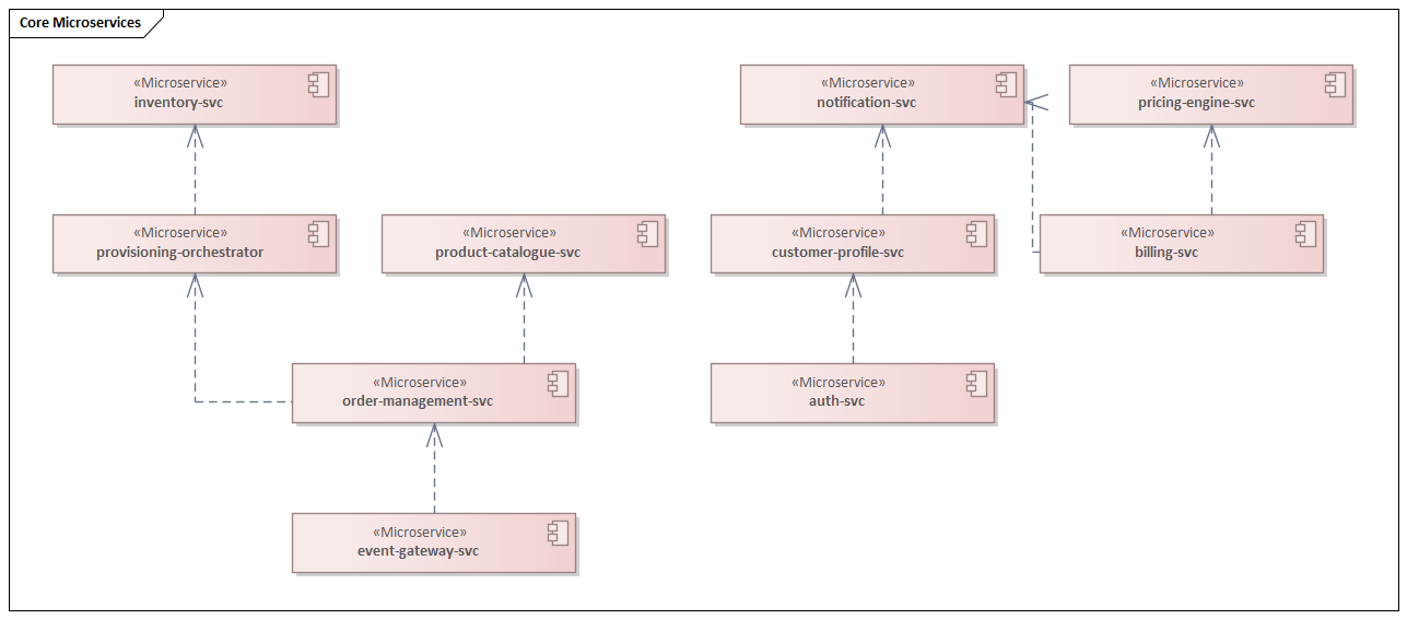
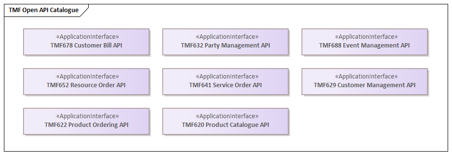
Each microservice realises one or more TM Forum Open API contracts. The order-management-svc implements TMF622 (Product Ordering API). The customer-profile-svc implements TMF629 (Customer Management API). The billing-svc implements TMF678 (Customer Bill API). The event-gateway-svc implements TMF688 (Event Management API). This alignment ensures that any third-party system — a partner portal, a digital marketplace, a wholesale customer — can integrate using a published, versioned standard without requiring a bespoke adapter.
TMF Open API Catalogue
Technology Architecture: Cloud, 5G and Kubernetes
The technology architecture layer defines the infrastructure platforms on which all application workloads run. It spans four domains: multi-cloud topology, 5G network functions, Kubernetes orchestration, and messaging platforms.
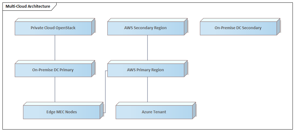
Multi-Cloud Architecture
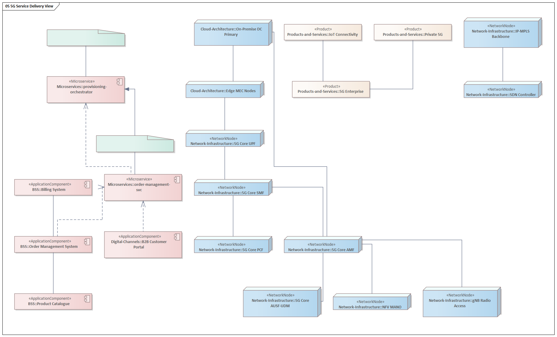
The operator runs a hybrid multi-cloud topology. AWS is the primary cloud provider, running in two regions for production workload high availability and disaster recovery. Azure hosts specific workloads — primarily Microsoft-stack integrations and Azure AD-based identity federation. On-premise data centres (primary and secondary) retain latency-sensitive 5G core functions, legacy systems pending migration, and data that cannot leave the premises for regulatory reasons. Edge MEC (Multi-access Edge Computing) nodes extend compute capacity to the radio access network, enabling ultra-low-latency applications for enterprise 5G customers.
5G Network Architecture
The 5G Core implements the 3GPP Release 16 service-based architecture. The Access and Mobility Management Function (AMF) handles all UE connection and mobility management. The Session Management Function (SMF) manages PDU session establishment. The User Plane Function (UPF) is the data path anchor that routes traffic between the radio access network and the data network. The Policy Control Function (PCF) enforces QoS and charging rules. The Authentication Server Function and Unified Data Management (AUSF/UDM) handle subscriber authentication and data.
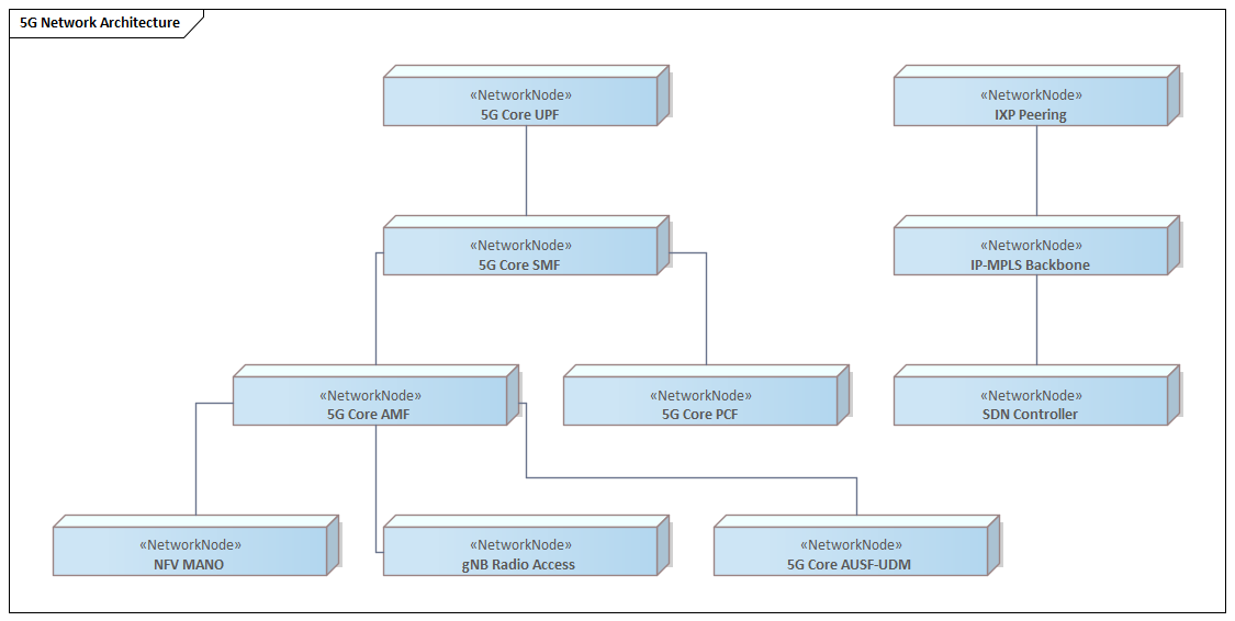
The SDN Controller provides the programmable abstraction layer over the IP-MPLS transport backbone, enabling automated network slice configuration for 5G enterprise customers. NFV MANO orchestrates the lifecycle of virtualised network functions. The combination of SDN and NFV is what makes 5G network slicing commercially viable — without it, provisioning an enterprise network slice takes weeks of manual configuration rather than minutes of API-driven automation.
Kubernetes Platform
All application workloads run on Kubernetes. The platform comprises four clusters — EKS Production, EKS Non-Production, On-Premise K8s, and Edge K8s — each managed through a unified GitOps deployment model using ArgoCD. Istio Service Mesh provides mutual TLS (mTLS) for all service-to-service communication within the production cluster, delivering the micro-segmentation required by Zero Trust architecture without changes to application code.
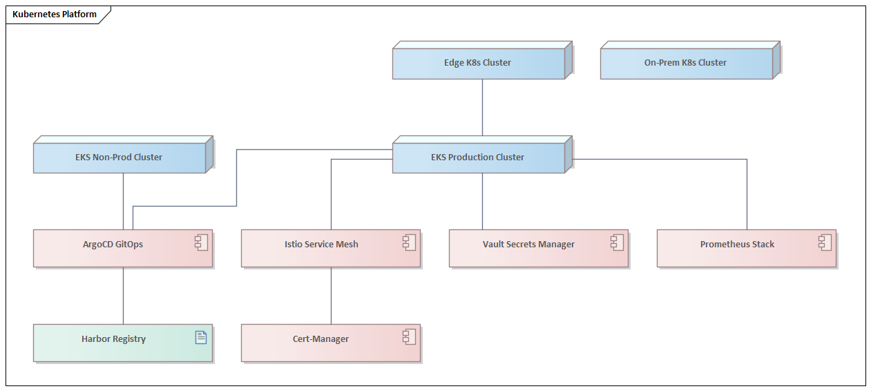
Vault Secrets Manager provides centralised secret management — no credentials are stored in application configuration or Kubernetes manifests. Cert-Manager automates TLS certificate lifecycle management. Prometheus Stack provides the observability foundation: metrics collection, alerting, and the data feed for the AIOps Engine. Harbor Registry is the private container registry that feeds the ArgoCD deployment pipeline.
Messaging Platforms
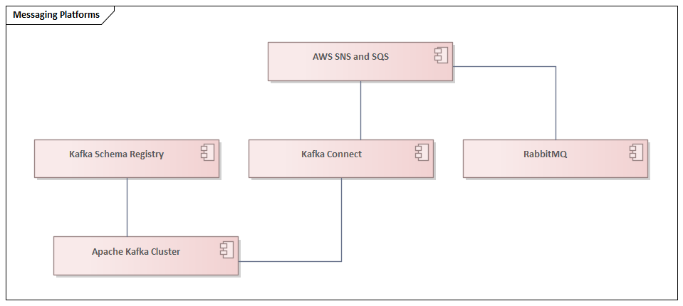
Apache Kafka is the enterprise event bus (ADR-001). The Kafka Schema Registry enforces Avro/Protobuf schema compatibility, preventing breaking changes to event contracts from silently corrupting downstream consumers. Kafka Connect bridges between Kafka and external systems — including the Data Lakehouse — for bulk data replication. The Dead Letter Queue captures events that cannot be processed, enabling operational replay and debugging without data loss.
Integration Architecture: APIs, Events and Patterns
Integration is where most telco transformation programmes fail. Systems are individually modernised but connected through point-to-point integrations that recreate the same tight coupling that made the legacy landscape unmaintainable. The integration architecture layer defines the patterns, platforms, and governance that prevent this failure mode.
API Gateway Landscape
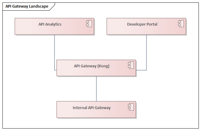
Kong is the API Gateway (ADR-003). All external API traffic — from partner portals, digital channels, wholesale customers, and third-party developers — enters the architecture through Kong. Kong enforces authentication (via the OAuth 2.0/OIDC Server), authorisation (via the RBAC/ABAC Engine), rate limiting, request transformation, and observability. The Developer Portal publishes API documentation, manages subscriptions, and provides a sandbox environment for third-party developers building on the TM Forum Open APIs.
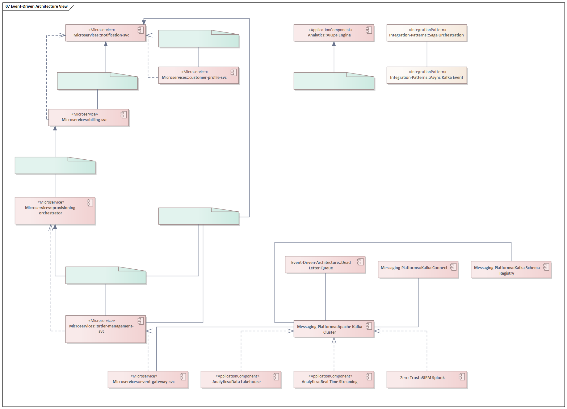
Event-Driven Architecture
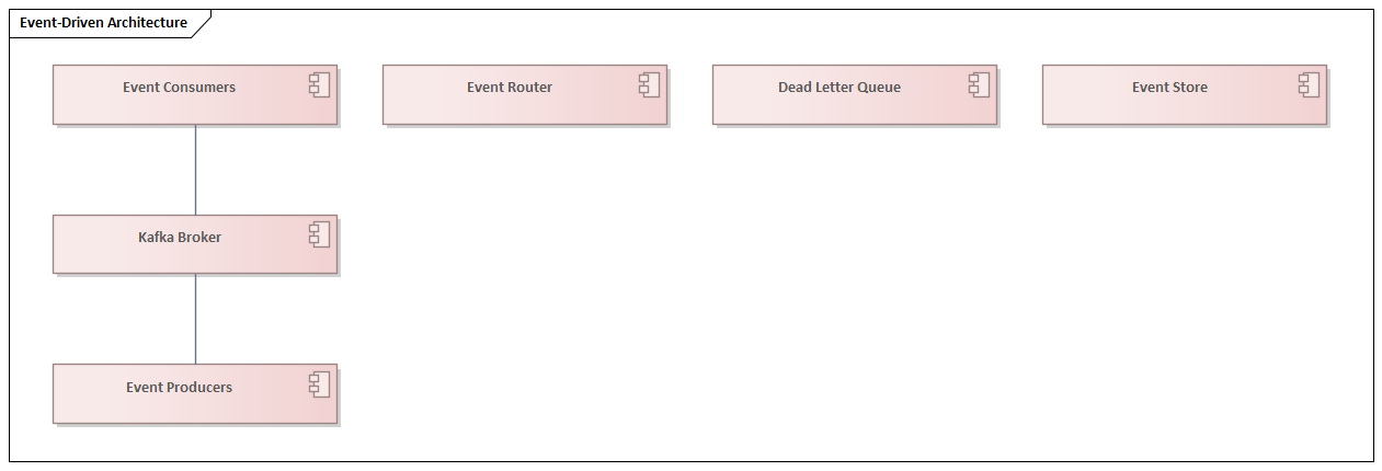
The event-driven architecture is structured around the CloudEvents v1.0 specification for event envelope standardisation. Twelve canonical events represent the core business events that flow between domains: customer.created, customer.updated, order.placed, order.completed, order.cancelled, service.activated, service.suspended, network.alarm.raised, network.alarm.cleared, invoice.generated, payment.received, and sim.swapped.
These events are not implementation details — they are architectural contracts. When the order.placed event is published, any number of consumers can react without the Order Management Service knowing or caring who they are. The Provisioning Orchestrator starts network configuration. The notification service sends a confirmation. The analytics platform records the transaction. The billing system begins usage tracking. This is the fundamental advantage of event-driven architecture over synchronous point-to-point integration: the publisher and consumers are fully decoupled in time and knowledge.
Integration Patterns
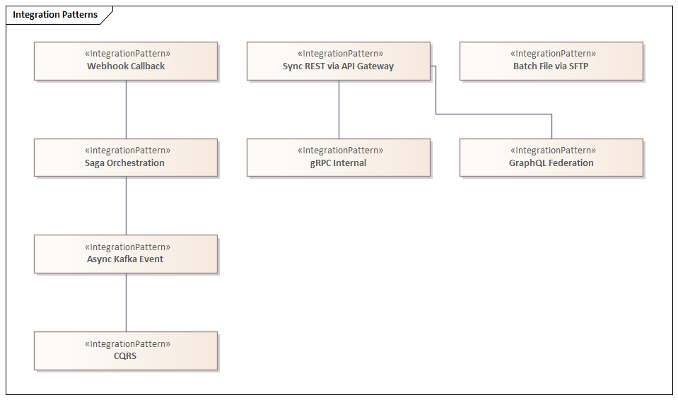
Not every integration should use the same pattern. The architecture defines eight canonical integration patterns, each appropriate for a specific context. Sync REST via API Gateway is appropriate for customer-facing queries where a real-time response is required and the operation is idempotent. Async Kafka Event is appropriate for state-change notifications where the publisher must not wait for consumer processing and where multiple consumers may need to react. Saga Orchestration is the pattern for long-running, multi-step business transactions — like Order-to-Activate — that must be coordinated across multiple microservices with compensating transactions for rollback. CQRS separates read and write models to optimise query performance in high-volume reporting scenarios without sacrificing write consistency.
Security Architecture: IAM and Zero Trust
Security in a modern telco is not a perimeter problem. The network perimeter dissolved the moment the operator started running workloads in public cloud, exposing APIs to third-party developers, and allowing employees to work from locations outside the corporate network. The architecture adopts Zero Trust as its foundational security model (ADR-010): no user, device, or service is trusted by default, regardless of network location.
Identity and Access Management

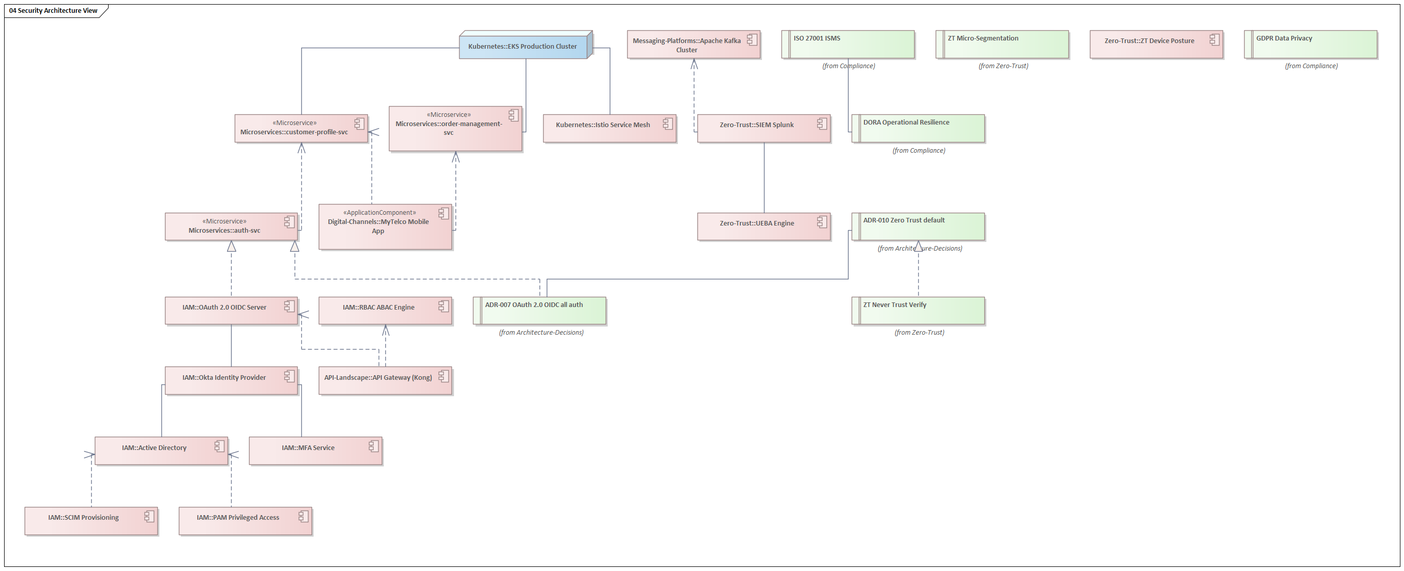
Okta is the Identity Provider (IdP) for all human users. Active Directory provides the authoritative source of user identity for employee accounts, federated into Okta via SCIM Provisioning. The OAuth 2.0/OIDC Server issues access tokens for both human users and machine-to-machine service accounts. The API Gateway delegates all authentication decisions to the OIDC Server — no authentication logic lives in application code. The RBAC/ABAC Engine enforces fine-grained authorisation policies based on role (who the caller is) and attribute (what they are trying to access, from where, and when). PAM (Privileged Access Management) enforces just-in-time, audited access to production systems for privileged users — no standing admin access.
Zero Trust Architecture
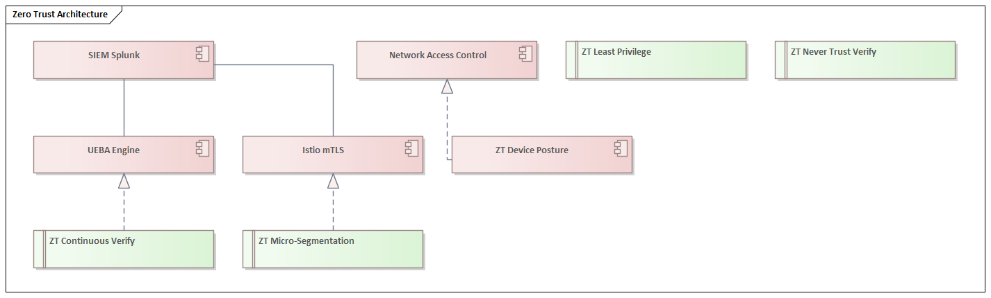
The Zero Trust architecture is organised around four principles, each realised by specific technology controls. Never Trust, Always Verify is realised by ADR-010 and the OIDC authentication mandate: every API call carries a signed JWT that is validated at the gateway, regardless of network origin. Least Privilege is realised by the RBAC/ABAC Engine: service accounts are granted only the minimum permissions required for their specific function. Micro-Segmentation is realised by Istio mTLS: even within the production Kubernetes cluster, service-to-service traffic is encrypted and authenticated, so a compromised pod cannot communicate laterally without a valid certificate. Continuous Verification is realised by the UEBA (User and Entity Behaviour Analytics) Engine, which feeds signals to SIEM Splunk for anomaly detection and automated response.
Solution Building Blocks and Programme Portfolio
Solution Building Blocks (SBBs) are reusable architectural patterns that encode the organisation’s preferred way of solving recurring problems. They bridge the gap between abstract architecture principles and concrete delivery — a development team implementing a new microservice should not need to rediscover how to configure the API Gateway, set up a Kafka consumer, or implement Zero Trust authentication. The SBB library codifies these decisions once and reuses them everywhere.
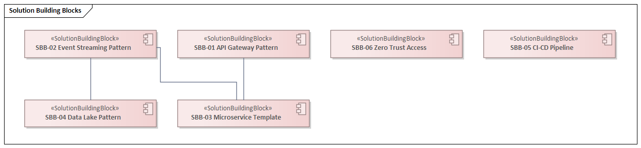
The six SBBs in this architecture cover the most frequently recurring patterns: the API Gateway Pattern (realised by Kong), the Event Streaming Pattern (realised by Apache Kafka), the Microservice Template (dependent on both the API Gateway and Event Streaming patterns), the Data Lake Pattern (dependent on Event Streaming), the CI/CD Pipeline (realised by ArgoCD), and Zero Trust Access (realised by Okta).
Transformation Roadmap
The transformation roadmap translates the strategic initiatives and programme portfolio into a sequenced delivery plan. Eight milestones span a three-year horizon from Q1 2025 to Q2 2027, each directly traceable to the strategic initiatives they realise.
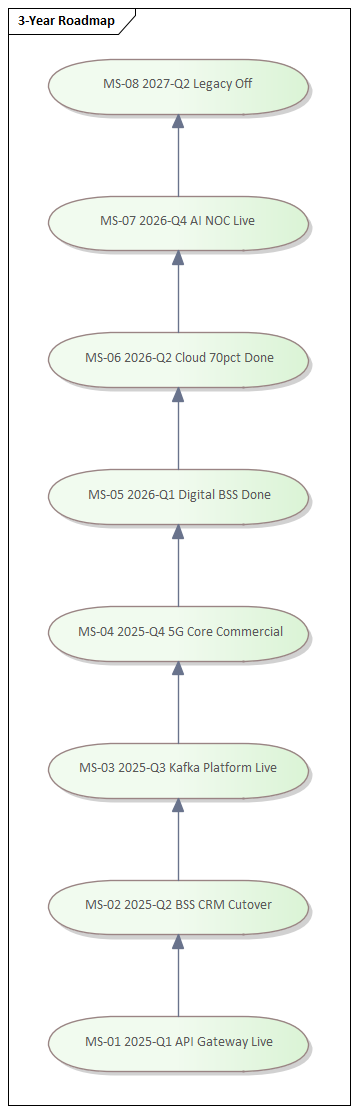
The sequencing is deliberate. The API Gateway going live in Q1 2025 is a prerequisite for exposing TM Forum Open APIs, which is in turn a prerequisite for the API Marketplace business model that SI-03 depends on. The Kafka Platform milestone in Q3 2025 must precede the AIOps programme in 2026, because the AIOps Engine requires a mature stream of operational events to train its models. The Legacy Off milestone in Q2 2027 is deliberately positioned after all replacement systems have been running in production for at least two quarters — no big-bang cutover, no single point of failure.
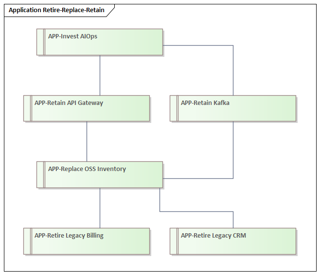
The application roadmap complements the milestone plan with a Retire/Replace/Retain/Invest classification for every application in the landscape:
Architecture Decisions and Referenced Standards
Architecture Decision Records (ADRs) are the mechanism through which the EA governance model makes decisions explicit, dated, and traceable. An ADR captures what was decided, why it was decided, what alternatives were considered, and what constraints it imposes on subsequent decisions. The architecture register contains ten ADRs covering the most significant decisions made to date.
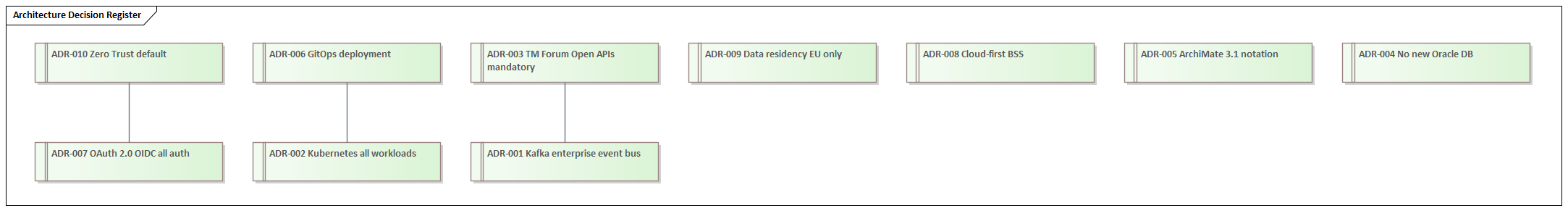
Each ADR is traceable in both directions: backwards to the EA Principle that motivates it, and forwards to the technology component that implements it. ADR-001 (Kafka as the enterprise event bus) is motivated by P01 (Design for Change) and P08 (Automate Everything), and is realised by the Apache Kafka Cluster. ADR-002 (Kubernetes for all workloads) is motivated by P03 (Cloud-Native by Default) and is realised by the EKS Production Cluster. ADR-010 (Zero Trust as default) is motivated by P05 (Security by Design), traces back to P05, and is realised by the Okta Identity Provider and the complete IAM/ZT stack.
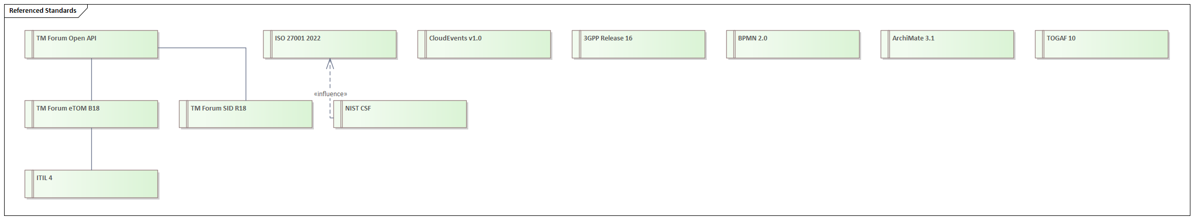
The Referenced Standards catalogue defines the external frameworks and specifications the architecture adopts. Eleven standards are referenced, covering process (TM Forum eTOM B18, ITIL 4), data (TM Forum SID R18), integration (TM Forum Open API, CloudEvents v1.0), modelling (ArchiMate 3.1, TOGAF 10, BPMN 2.0), security (ISO 27001 2022, NIST CSF), and network (3GPP Release 16). ArchiMate layers explained
Cross-Cutting Master Views
The most powerful capability of a properly connected EA repository is the ability to generate cross-cutting views that show multiple architecture layers simultaneously. These master diagrams are not possible without the underlying relationships — they are what justifies the investment in modelling the connections, not just the elements.
Order-to-Activate Flow
BSS-OSS Integration View
Security Architecture View
5G Service Delivery View
Data Flow and CDM View
Event-Driven Architecture View
Strategy to Delivery Traceability
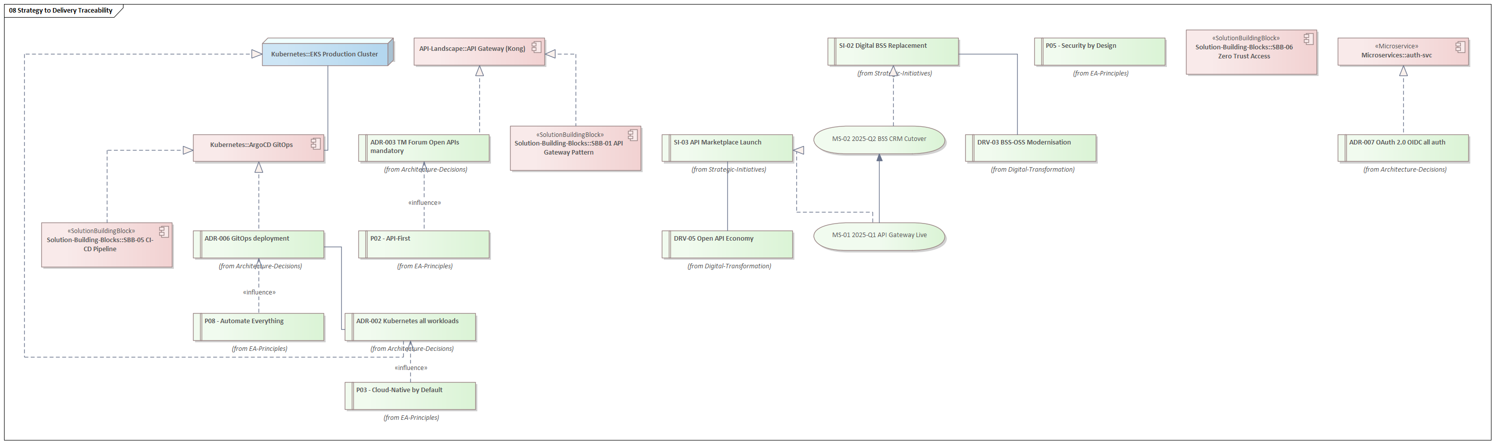
This last diagram encapsulates the fundamental value of an Enterprise Architecture repository: the ability to stand in a board meeting with a strategic initiative and trace it, unambiguously and completely, down through the decision chain to the specific technology component delivering it, and back up through the compliance controls governing it. That is what justifies every hour invested in maintaining the model.
Conclusion: Architecture as a Competitive Weapon
The architecture described in this article is not theoretical. Every diagram was generated from a real, executable Sparx EA model built with automated JScript — a model that can be maintained, extended, queried, and reported against as the transformation programme progresses. It demonstrates what is possible when Enterprise Architecture is treated not as a governance overhead but as an engineering discipline applied to the organisation itself. free Sparx EA maturity assessment
Several themes run through the entire repository and deserve to be restated explicitly.
Traceability is the product. The value of this model is not in any individual diagram — it is in the connections between them. A strategic driver that cannot be traced to a capability gap that cannot be traced to an application investment that cannot be traced to a delivery milestone is not an architecture input; it is wishful thinking. Every relationship in this model was created deliberately to preserve that thread.
Standards alignment is not compliance theatre. The alignment to TM Forum eTOM, SID, and Open APIs is not a checkbox exercise. It means that when this operator integrates with a partner, a wholesale customer, or a cloud provider, the interface contracts are already defined and publicly documented. It eliminates negotiation, accelerates delivery, and reduces the cost of every future integration.
Zero Trust is not a security product — it is an architectural model. The Zero Trust architecture described here is not achieved by buying a single platform. It is the cumulative effect of Kubernetes micro-segmentation, Istio mTLS, OAuth 2.0/OIDC authentication, RBAC/ABAC authorisation, UEBA anomaly detection, and PAM privileged access — each implemented in its correct layer, each traceable back to the P05 Security by Design principle.
Automation is the only sustainable operating model. At the scale of a modern telco — thousands of microservice instances, millions of events per second, hundreds of network changes per day — manual operations are not slower than automated ones; they are categorically impossible. The GitOps deployment model, the AIOps Engine, the Saga Orchestration pattern, and the CI/CD pipeline SBB are not conveniences — they are the only way a team of humans can operate this architecture reliably.
If you are building or modernising a telco EA practice, or if you are using Sparx Enterprise Architect to model a complex enterprise, the patterns and structures described here provide a tested starting point. The full model was built with ArchiMate 3.1, governed by TOGAF 10 principles, and aligned to the TM Forum Open Digital Framework. The automation script that generated it is a reusable foundation for any operator willing to treat their architecture as a living, executable asset rather than a slide deck.
Enterprise Architecture without cross-cutting traceability is interior design. Every element looks fine in isolation; nothing works together as a system. The discipline is in the connections, not the boxes.
Frequently Asked Questions
What is Sparx Enterprise Architect used for?
Sparx Enterprise Architect (Sparx EA) is a comprehensive UML, ArchiMate, BPMN, and SysML modeling tool used for enterprise architecture, software design, requirements management, and system modeling. It supports the full architecture lifecycle from strategy through implementation.
How does Sparx EA support ArchiMate modeling?
Sparx EA natively supports ArchiMate 3.x notation through built-in MDG Technology. Architects can model all three ArchiMate layers, create viewpoints, add tagged values, trace relationships across elements, and publish HTML reports — making it one of the most popular tools for enterprise ArchiMate modeling.
What are the benefits of a centralised Sparx EA repository?
A centralised SQL Server or PostgreSQL repository enables concurrent multi-user access, package-level security, version baselines, and governance controls. It transforms Sparx EA from an individual diagramming tool into an organisation-wide architecture knowledge base.