⏱ 25 min read
UML Modeling Best Practices for Software Architects | Architecture Guide Sparx EA guide
Discover UML modeling best practices for software architects, including diagram selection, consistency, stakeholder communication, and maintainable architecture documentation. Sparx EA best practices
UML modeling best practices, UML for software architects, software architecture documentation, UML diagrams, architecture modeling, system design best practices, enterprise architecture UML, technical architecture diagrams, UML standards, software design communication how architecture review boards use Sparx EA
Introduction
Unified Modeling Language (UML) still earns its place in the architect’s toolkit. Not because every project needs a full set of diagrams, and not because strict notation has value on its own, but because good models make architecture understandable. They help people see structure, behavior, boundaries, dependencies, and operational risk quickly enough to make decisions with confidence. In enterprise settings—where solutions cut across products, shared platforms, governance controls, vendors, and delivery teams—that clarity is hard to achieve with prose alone.
The most common mistake is to treat UML as either heavyweight documentation or a developer-only design artifact. In practice, it is neither. UML is most effective when it sits between those extremes: detailed enough to remove ambiguity, restrained enough to stay useful. Architects should model when a diagram resolves uncertainty that text leaves open: who owns what, where an integration boundary starts, how a runtime flow behaves under failure, or what the deployment topology implies for resilience and security. The point is not to document everything. The point is to make important decisions visible.
A simple example makes the case. Suppose an architecture review board is deciding whether a new customer service can call an ERP platform directly or must go through an API layer. Several pages of narrative may describe the options, but a single component diagram will usually settle the discussion faster. It shows the dependency path, the coupling introduced by direct access, and the governance boundary the API layer is meant to preserve.
This becomes more important when architecture has to be communicated at different levels of abstraction. Executives usually want to understand business boundaries, capability relationships, and risk concentration. Delivery teams need clearer views of service responsibilities, interfaces, and interaction flows. Security and operations teams need trust zones, network transitions, runtime placement, and deployment dependencies. UML helps architects tailor those views without telling different stories to different audiences.
It also exposes weaknesses early. A component diagram can reveal unclear ownership or unhealthy dependency patterns. A sequence diagram can uncover orchestration that looks simple in conversation but becomes fragile once retries, timeouts, and exception paths are shown. A deployment diagram can bring network boundaries, failover assumptions, and scaling limits into view before they become production issues. Used this way, UML does more than describe architecture. It pressure-tests it.
Modern delivery practices demand a pragmatic approach. In agile, cloud-based, product-oriented environments, architects should favor just-enough modeling: diagrams that support decisions, stay current, and can be maintained without ceremony. Large repositories of exhaustive models usually decay faster than the systems they describe. A smaller set of focused views, tied to design reviews, delivery milestones, and governance checkpoints, is far more sustainable.
The core principle of this article is straightforward: UML works best when it is used with intent. Choose diagrams based on the decisions they support, keep each view centered on a single concern, and maintain only the models that materially improve delivery, governance, or operational understanding. The sections that follow build on that principle by examining why UML still matters, how to choose the right diagrams, how to model clearly, how to connect architecture domains, what mistakes to avoid, and how to govern UML at enterprise scale.
Why UML Still Matters in Modern Enterprise Architecture
UML is sometimes dismissed as a relic from a more document-heavy era. That criticism misses the point. As enterprise landscapes become more distributed, the need for precise architectural communication grows rather than shrinks. Hybrid cloud estates, SaaS ecosystems, internal platforms, event brokers, APIs, packaged applications, and regulatory controls create a level of complexity that informal sketches and narrative documents rarely handle well on their own. UML still matters because it gives architects a disciplined way to express that complexity without forcing readers to infer design intent from paragraphs of text.
Its real value is not formality. It is separation of concerns. Enterprise systems rarely fail because no one wrote anything down. More often, they fail because too many concerns are blended together in ways that blur the decision at hand. A conversation about business capability boundaries is not the same as a conversation about runtime resilience. A review of application ownership is not the same as a review of trust zones. UML helps isolate those concerns into views that are easier to discuss, challenge, and approve.
That matters in federated delivery environments, where few solutions are owned end to end by a single team. Architects often have to align domain teams, platform teams, vendors, and governance functions around shared interfaces and responsibilities. In that setting, ambiguity is expensive. A well-constructed model can show which service owns a capability, where an integration boundary begins, which dependencies are contractual, and which interactions are synchronous versus asynchronous. Those distinctions affect sequencing, funding, nonfunctional requirements, and operational accountability.
Consider an IAM modernization program. Identity services, HR systems, directories, SaaS applications, and access governance tools all have different owners. Without a clear model, discussions drift into local assumptions: HR assumes identity is downstream, security assumes provisioning is policy-driven, application owners assume access requests are manual exceptions. A focused set of UML views can make the operating reality visible: HR is the source of truth for joiner events, the identity platform orchestrates provisioning, directory synchronization remains transitional, and selected SaaS platforms still require approval workflows. That level of clarity changes the quality of planning.
UML also helps bridge conceptual architecture and engineering execution. Enterprise architecture often defines target states, principles, and domain boundaries, while delivery teams need something more concrete: components, interactions, deployment implications, and operational constraints. UML can connect those layers. A high-level component diagram may show how a capability is partitioned across systems; a supporting sequence diagram can reveal latency risks or trust transitions; a deployment diagram can then expose where resilience assumptions rely on infrastructure topology. That continuity keeps architecture from drifting into abstraction that no longer influences delivery.
There is a governance benefit as well. Reviews slow down when solution descriptions are narrative-heavy, inconsistent, or open to interpretation. A disciplined UML model gives reviewers a common surface to inspect. Security teams can assess trust boundaries and communication paths. Operations teams can evaluate dependency concentration and runtime topology. Integration reviewers can look at protocol choices and coupling patterns. Instead of asking each stakeholder to interpret the architecture from text, UML makes the key design choices inspectable.
Its usefulness, however, depends on restraint. UML is not valuable because it can describe everything. It is valuable because it can describe the right things at the right level of precision. A lightweight component diagram may be enough for early alignment. A detailed sequence diagram may be necessary for a payment authorization flow where retries, compensation, and external dependencies matter. UML remains relevant because it adapts to the decision being made while preserving a common language across stakeholders.
Choosing the Right UML Diagrams for Architectural Communication
If UML is most useful when it supports a specific decision, then the first question is not how much detail to include. It is whether a diagram should exist at all. UML offers many diagram types, but only a handful are consistently useful in software architecture. The right choice depends on the question being answered, the audience reading the model, and the action the diagram is meant to support.
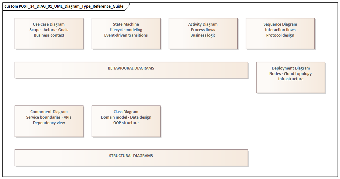
A practical way to think about diagrams is as viewpoint instruments rather than documentation categories. Each should illuminate one concern clearly. If the concern is responsibility and dependency, use a component diagram. If the concern is runtime behavior, sequencing, timing, or failure handling, use a sequence diagram. If the concern is infrastructure placement, network boundaries, failover design, or environment topology, use a deployment diagram. If the concern is early scoping of actors and interactions, a lightweight use case diagram can help—provided it remains tied to the broader architecture.
Component diagrams
For most architects, the component diagram is the core architectural artifact. It sits at the point where structure meets responsibility and is often the most useful place to start. A good component diagram shows bounded services, major internal modules, exposed interfaces, key external dependencies, and ownership boundaries without collapsing into implementation detail. Sparx EA training
In enterprise settings, component diagrams are especially valuable because they make accountability visible. They show where shared platforms begin, which teams own which services, and which integrations are formal contracts rather than incidental dependencies. They also reveal dependency direction and likely change impact. ArchiMate relationship types
Take a pricing platform review. The architecture board may be comfortable approving separate ownership for Pricing Service and Promotion Service, but reject a proposed direct dependency from the web channel into the rules engine. The decision is not about notation. It is about preserving a stable API boundary. A component diagram makes that boundary explicit and gives the board something concrete to approve or reject.
Sequence diagrams
Sequence diagrams become essential when behavior matters more than structure. They are particularly useful for high-risk or business-critical flows such as onboarding, claims processing, payment authorization, order submission, and identity verification. Their value lies in making orchestration visible: synchronous versus asynchronous calls, retries, timeouts, exception handling, trust transitions, and external dependencies.
They are often the best tool for exposing architectural fragility. A design may look clean in a component view, yet become brittle once the interaction flow is drawn. An orchestrator may depend on too many synchronous calls. A user journey may cross several trust boundaries. A fallback path may be missing entirely.
A realistic example comes from retail order processing. A sequence diagram for “submit order” might show the web channel calling Order Service, which reserves inventory asynchronously through an event, requests payment authorization synchronously, and only then emits an OrderConfirmed event. That sequence makes two things visible immediately: customer confirmation depends on the payment provider’s latency, and warehouse allocation is eventual rather than transactional. Those are architecture decisions, not implementation trivia.
Deployment diagrams
Deployment diagrams are often underused, even though many architecture problems are ultimately runtime problems. In cloud and hybrid environments, issues often arise not from component logic but from placement, connectivity, failover assumptions, and boundary control. A deployment view can show what runs in managed cloud services, what remains on premises, where ingress and egress occur, how environments differ, and where resilience depends on infrastructure topology.
These diagrams are particularly useful for security, infrastructure, and operations stakeholders. A logical application view may be enough for a design discussion, but it is rarely enough for a review of trust zones, network paths, or operational recovery assumptions.
A common enterprise example is a reporting solution where transactional data remains on premises while analytics workloads run in the cloud. A deployment diagram can show the data replication path, the network boundary crossed, the managed services involved, and the point at which data leaves the regulated zone. That one view often surfaces questions about encryption, latency, and recovery that would otherwise appear much later.
Use case diagrams and selective support views
Use case diagrams can help during early scoping, especially when role boundaries and user interactions are still being clarified. Their role is limited but useful: frame the business interaction, identify actors, and establish scope. They should not become a substitute for clearer application or runtime views.
Architects should also know when not to use UML. Sometimes a context map, decision table, matrix, or architecture decision record communicates the issue more directly. UML should support architectural communication, not dominate it. The strongest architecture documents usually combine a small number of UML views with concise narrative and explicit rationale.
A simple selection test
Before creating any diagram, ask three questions:
- What decision does this diagram support?
- Which stakeholder concern does it address?
- What level of detail is necessary to act on it?
If those questions are answered clearly, the right diagram type usually follows. If they are not, the diagram probably should not be created yet.
Modeling Best Practices for Clarity, Consistency, and Maintainability
Choosing the right diagram is only the beginning. The quality of a UML model depends on how quickly and accurately stakeholders can read it. A diagram should reduce interpretation effort, not increase it. That requires discipline in scope, naming, abstraction, layout, and upkeep.
Keep each diagram focused
Each diagram should answer one primary question. When a single view tries to explain business context, internal design, runtime behavior, security boundaries, and deployment topology all at once, it usually fails at all of them. A small set of focused diagrams is almost always more effective than one overloaded artifact.
Titles and scope statements help more than many teams realize. “Logical component view for customer onboarding” tells the reader what they are looking at. “Architecture diagram” tells them almost nothing.
Use a consistent vocabulary
Inconsistent naming quickly erodes trust. Terms such as service, application, platform, domain, module, and component should not be used interchangeably unless the architecture explicitly defines them that way. If “Customer Profile Service” appears in the component model, the same label should appear in related sequence and deployment views unless there is a deliberate reason to distinguish logical and physical forms.
This is not a cosmetic issue. Shared vocabulary is what turns separate diagrams into a coherent architectural narrative. Without it, readers spend their energy translating instead of understanding.
Make abstraction levels explicit
Many UML models become misleading because they mix conceptual, logical, and physical elements without making the transition clear. A business capability, a microservice, a Kubernetes cluster, and a vendor SaaS product should not appear side by side as though they belong to the same modeling layer unless the diagram is intentionally cross-layer and clearly labeled as such.
Architects should decide what level a diagram represents and state it plainly. If cross-layer relationships are necessary, they should be intentional and visually differentiated. This is especially important in enterprise environments, where confusion between target-state concepts and implementation-specific design can create friction in both governance and delivery.
Apply visual discipline
Layout is not decoration. It carries meaning. Related elements should be grouped predictably, dependency direction should be easy to follow, and line crossings should be minimized. Interfaces, external systems, and trust boundaries should be visually distinct. Excessive styling usually makes diagrams harder to read and harder to maintain.
A restrained visual style is also easier to govern across teams. The more a model depends on custom conventions and tool-specific tricks, the harder it becomes for others to reuse and update it.
Tie diagrams to decisions
Diagrams stay current when they exist for a reason. A useful model should be anchored to a decision: domain ownership, resilience strategy, integration sequencing, environment segregation, or a similar concern. When that concern changes, the associated diagram should change with it.
That is why effective architecture teams link diagrams to decision records, backlog items, review gates, or release milestones. A model that is disconnected from delivery and governance activity is far more likely to become stale.
For instance, if an enterprise integration standard changes and requires domain events to be published through Kafka rather than point-to-point messaging, the affected component and sequence views should be updated as part of that decision. If the update is deferred indefinitely, the model stops being architecture and becomes historical fiction.
Add selective annotations
UML notation can show that one component depends on another, but it often cannot explain whether the dependency is strategic, temporary, or a known compromise. Short notes can add just enough context without overwhelming the diagram.
This is particularly useful in transformation programs. A platform may still call a legacy master data service for six months while a new domain service is being introduced. If that dependency is transitional, mark it. Reviewers should not have to infer whether they are seeing target state, interim state, or technical debt.
Model for stewardship
Architects should create diagrams that others can understand and maintain after the original author has moved on. That means using standard notation where it matters, documenting key conventions, and avoiding unnecessarily tool-specific constructs. A maintainable UML practice supports continuity across teams and over time, not just the preferences of one architect.
Using UML to Bridge Business, Application, Data, and Technology Architectures
One of UML’s most useful roles in enterprise architecture is as a translation layer across domains that are often documented separately. Business architecture describes capabilities, actors, and processes. Application architecture focuses on systems, services, interfaces, and responsibilities. Data architecture deals with information ownership, lifecycle, and movement. Technology architecture covers platforms, hosting models, networks, and operational constraints. These perspectives are interdependent, yet in many organizations they are still produced in isolation. UML helps connect them.
The goal is not to force every concern into one diagram. The goal is traceability across focused views. A business interaction can be framed in a lightweight use case or activity-oriented view. A component diagram can show which applications or services realize that interaction. A sequence diagram can then show how information moves during execution. A deployment diagram can expose the technology footprint, trust zones, and runtime constraints behind that flow. When those views align, stakeholders can follow a clear path from business objective to implementation reality.
Connecting business intent to application design
This is particularly valuable in capability-based planning. Enterprises often define target capabilities at a strategic level but struggle to connect them to concrete system changes. UML can help map a capability to the services that enable it and the interactions that make it real.
Consider a “Real-Time Order Visibility” capability. On paper, it sounds like a business requirement. In practice, it may depend on order services, warehouse systems, event streaming infrastructure, customer reference data, and mobile channels. Modeling those relationships forces hidden dependencies into the open and gives roadmap discussions a firmer basis.
Making data concerns architecturally visible
Data architecture is often underrepresented until integration or reporting issues appear late in delivery. UML does not replace formal data modeling, but it can make data concerns visible where they matter architecturally. In component and sequence views, architects can show system-of-record ownership, canonical versus local representations, transformation points, replication patterns, and event propagation paths.
This is especially important in distributed architectures, where user-facing processes appear unified while the underlying data remains fragmented across domains and platforms. A sequence diagram that shows where data is enriched, transformed, or propagated asynchronously can reveal consistency risks that a static logical view would miss.
A good example is an event-driven order platform. Order Service publishes OrderPlaced, Inventory Service consumes it, Billing Service reacts to the same event, and Notification Service sends customer updates independently. A simple sequence view can make one crucial point visible: customer confirmation is eventual and depends on downstream processing, not on a single transaction spanning all services. That distinction has direct implications for user messaging, reconciliation, and support processes.
Connecting technology choices to business impact
Technology architecture becomes more meaningful when it is tied back to business and application context. Platform decisions such as cloud adoption, containerization, managed services, or zero-trust networking are often presented too abstractly. UML can connect those choices to operational consequences.
For example, a deployment diagram may show that a customer authentication journey crosses an identity provider in the cloud, an on-premises directory, and a third-party fraud service. That one view tells security reviewers where trust zones change, tells operations where latency may accumulate, and tells the business where a customer login depends on external availability. The technology choice is no longer abstract. Its business impact is visible.
Model around scenarios, not silos
In practice, bridging architecture domains works best when architects model around a business scenario rather than around organizational silos. Start with an important flow, identify the business outcome, then connect the enabling applications, critical data exchanges, and supporting technology footprint. The resulting artifacts are usually more useful for transformation planning, design review, and stakeholder alignment than domain-specific diagrams created in isolation.
This approach also exposes accountability gaps. If a business capability spans several systems but no team owns the end-to-end outcome, the model will show it. In that sense, UML supports organizational clarity as much as technical clarity.
Common UML Modeling Mistakes Software Architects Should Avoid
The same qualities that make UML useful—structure, flexibility, and broad applicability—also make it easy to misuse. Most failures come not from the notation itself but from poor choices about scope, intent, and interpretation. The following mistakes are common in enterprise architecture.
Creating “master diagrams”
One of the most frequent errors is trying to capture everything in a single diagram. Architects attempt to show every application, interface, environment, exception path, and stakeholder concern in one view. The result is dense, difficult to review, and too brittle to maintain. Excessive completeness creates the appearance of rigor while hiding the risks the model should expose.
Separate concerns. Let each view support one architectural conversation well.
Prioritizing notation over usefulness
A diagram can be formally correct in UML terms and still fail as an architecture artifact. Teams sometimes spend more time debating symbols and stereotypes than clarifying ownership, dependency direction, runtime boundaries, or failure handling. Notation matters, but only insofar as it improves comprehension. Precision should support understanding, not replace it.
Presenting assumptions as decisions
Early-stage diagrams often blur the line between confirmed decisions, assumptions, and target-state aspirations. That can mislead delivery teams and distort governance reviews. If an event-driven integration is shown as though it already exists when it is only planned, downstream design may be built on capabilities that are not yet available.
Architects should mark transitional states, unresolved dependencies, and planned evolutions explicitly. The same applies to technology lifecycle governance. If a diagram presents a legacy ESB or database platform as strategic when it is actually scheduled for retirement, the model is doing real damage.
Modeling only the happy path
A clean sequence flow can suggest predictable interactions while leaving out retries, timeouts, asynchronous delays, compensating actions, or third-party failures. In enterprise systems, those omitted conditions are often where the true architecture risk sits. Happy-path-only models can unintentionally validate brittle designs.
For high-risk flows, include at least the major exception or fallback conditions that materially affect resilience, user experience, or support.
Hiding important boundaries
Many diagrams show components but fail to make trust zones, ownership lines, data residency constraints, or third-party dependencies visually obvious. That weakens their value for security, compliance, and operational review. In enterprise architecture, boundaries are often more important than components because they determine how risk, responsibility, and change propagate.
Letting tools drive the model
Some teams produce diagrams that reflect the defaults of a modeling tool rather than the needs of the architecture discussion. The result is autogenerated clutter, unnecessary stereotypes, and repository structures that only specialists can navigate. Architects should control the message and use tools to support it, not the reverse. free Sparx EA maturity assessment
Treating UML as a one-time deliverable
Diagrams created only for approval checkpoints quickly drift away from implementation and operational reality. Once that happens, teams stop trusting them and governance becomes performative. The most important models should be revisited when major decisions, dependencies, or deployment assumptions change. The goal is not perfection. It is continued credibility.
Governance, Collaboration, and Tooling for Enterprise-Scale UML Adoption
For UML to deliver consistent value at enterprise scale, it needs operating discipline as well as individual skill. In small teams, useful diagrams can emerge informally. In larger organizations, the harder problem is stewardship: who defines conventions, how models are reviewed, where they are stored, how they evolve, and how they remain usable across teams and portfolios.
Define a lightweight modeling standard
A sound governance approach starts with a small set of shared conventions. This does not require a rigid enterprise meta-model for every initiative. It does require clarity on common diagram types, naming rules, annotation patterns, color usage, and expectations for showing ownership, trust boundaries, and lifecycle state.
The aim is consistency without bureaucracy. Reviewers should not have to relearn the visual language every time they open a new solution design.
Make accountability explicit
Diagrams become stale when ownership disappears after the initial design phase. A more effective pattern is to assign stewardship by view. A solution architect may own the logical component model, a platform architect may maintain deployment views, and delivery teams may update sequence diagrams for critical flows. Governance should review not only model quality but also whether ownership and update triggers are clear.
Treat UML as a collaborative working surface
Enterprise architecture is rarely authored by one role alone. UML becomes more valuable when architects, engineers, security specialists, operations teams, and product stakeholders use it together. That means diagrams should sit in workflows that support comments, version history, change proposals, and links to related decisions.
When a model can be reviewed alongside an architecture decision record, an API contract, a resilience requirement, or a backlog item, it becomes part of active architecture practice rather than passive documentation.
Choose tools for accessibility, not just notation depth
At enterprise scale, the best UML tool is not necessarily the one with the richest feature set. It is the one that balances rigor, accessibility, integration, and maintainability. If only a small group of specialists can edit or interpret models, adoption will remain narrow.
Useful tooling should support shared repositories, role-based access, exportable review views, version control integration, and traceability to delivery and governance artifacts. In many organizations, compatibility with documentation platforms and engineering toolchains matters more than exhaustive UML support.
Support federated modeling
Fast-moving product teams and centrally governed architecture functions often need different levels of formality. A practical enterprise pattern is federated modeling: core reference models are centrally governed, while solution-specific diagrams are maintained by delivery teams within agreed standards. This preserves consistency without turning architecture into a centralized bottleneck.
Manage model lifecycles
Not all diagrams should live forever. Some are strategic and long-lived, such as reference architectures, domain interaction maps, or standard deployment patterns. Others are transitional and should expire after a migration or release phase. Making lifecycle status explicit helps prevent repositories from filling with outdated artifacts that dilute trust.
This is particularly important in technology lifecycle governance. If a database engine is in tolerate status for twelve months and then moves to retire, that state should be visible in reference deployment and platform diagrams so solution teams do not design new dependencies onto a shrinking platform.
At scale, successful UML adoption depends less on drawing technique than on institutionalizing how models are governed, shared, tooled, and sustained.
Conclusion
UML delivers the most value when architects use it as a decision-support tool rather than a compliance artifact. In enterprise environments, the problem is rarely the absence of diagrams. More often, it is the absence of models that remain relevant as the architecture changes. That is why purposeful modeling matters.
The strongest UML practice is selective. Choose the smallest set of views that clarifies structure, behavior, boundaries, and operational implications. Use component diagrams to establish responsibility and dependency. Use sequence diagrams to test critical interactions and failure-sensitive flows. Use deployment diagrams to expose runtime realities. Keep each view focused, use consistent vocabulary, make abstraction levels explicit, and connect diagrams to real decisions.
Just as important, treat UML as part of architecture execution. A useful model should influence team boundaries, interface design, resilience strategy, security review, deployment planning, and governance outcomes. If it does not help people make better decisions, it is probably unnecessary.
UML remains relevant because enterprise architecture still depends on shared understanding across diverse stakeholders, technologies, and planning horizons. Used well, it reduces ambiguity without creating unnecessary documentation, surfaces risk before delivery, and preserves coherence through change. The best practice is not to model more. It is to model with purpose, maintain what matters, and make sure every diagram earns its place in the architecture story.
Frequently Asked Questions
What UML diagram types are most useful for enterprise architects?
For enterprise architecture: Component diagrams (application structure and interfaces), Deployment diagrams (infrastructure topology), Sequence diagrams (runtime interactions), Class diagrams (domain models and data structures), and Use Case diagrams (functional scope). Each serves a different audience and purpose.
What are the most common UML modeling mistakes?
Common mistakes include: using the wrong diagram type for the audience, mixing abstraction levels in a single diagram, over-specifying implementation detail in structural diagrams, omitting multiplicities and relationship types, and creating diagrams that are not navigable or meaningful outside their original context.
How does UML relate to ArchiMate in enterprise architecture?
UML and ArchiMate are complementary. ArchiMate is used for enterprise-wide architecture across business, application, and technology layers. UML is used for software design — class structures, sequences, components, and deployments within a single application or domain. In Sparx EA, both notations coexist in the same repository.